|
|
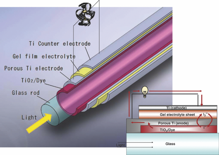
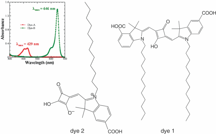
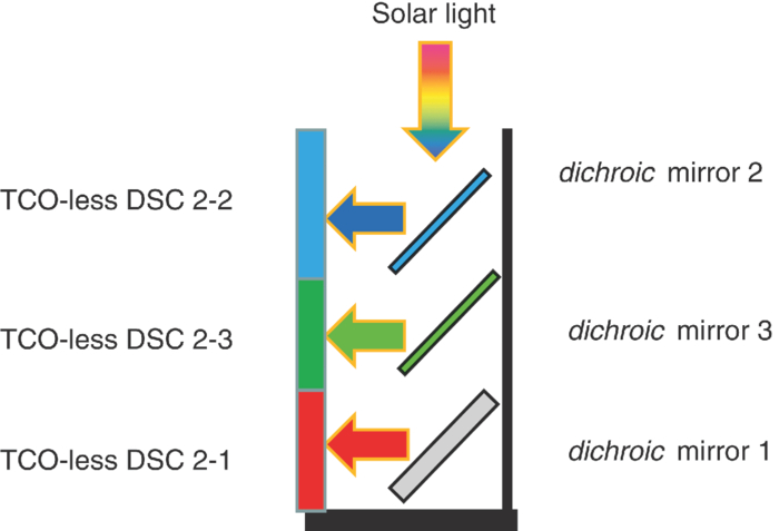
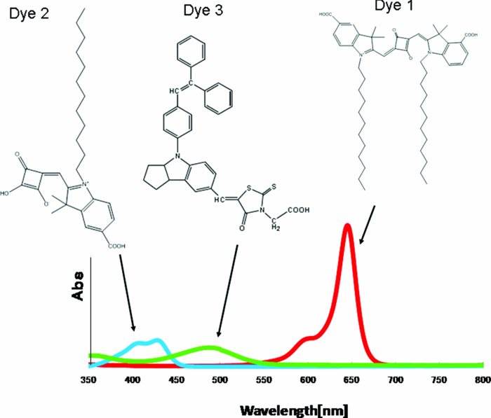
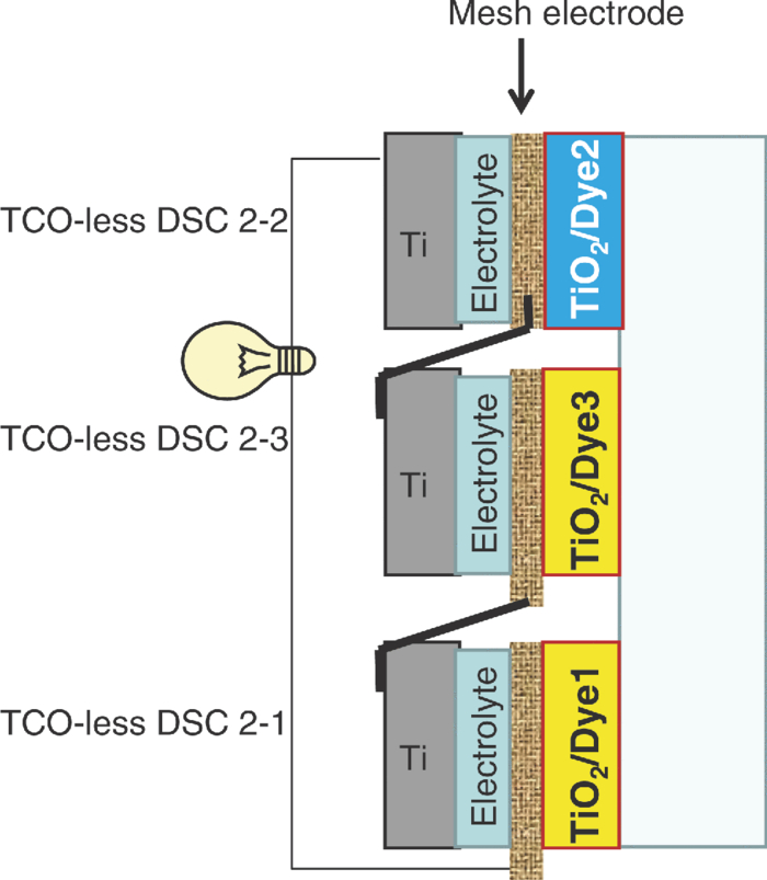
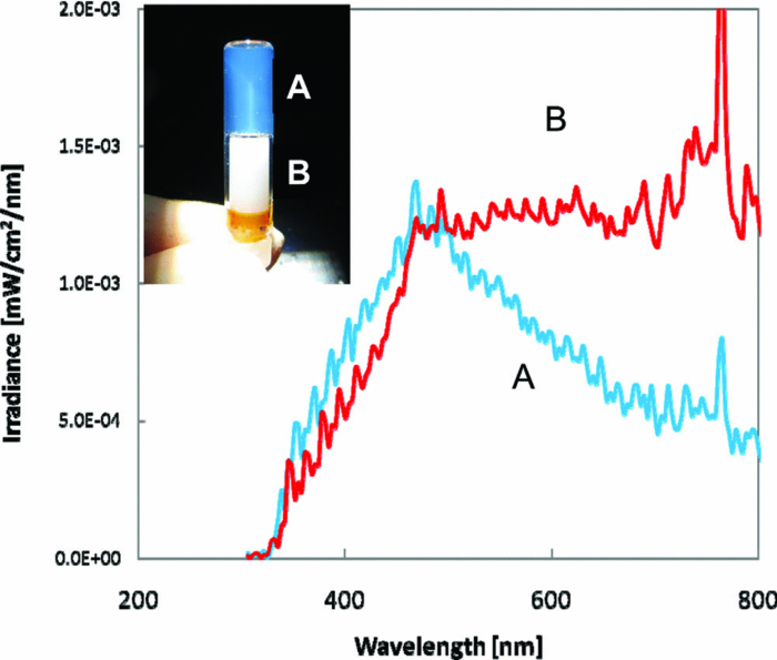
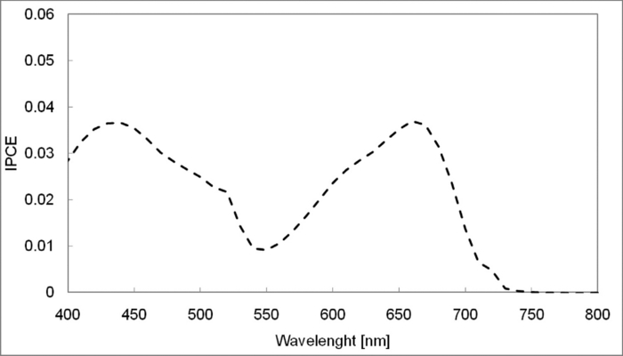
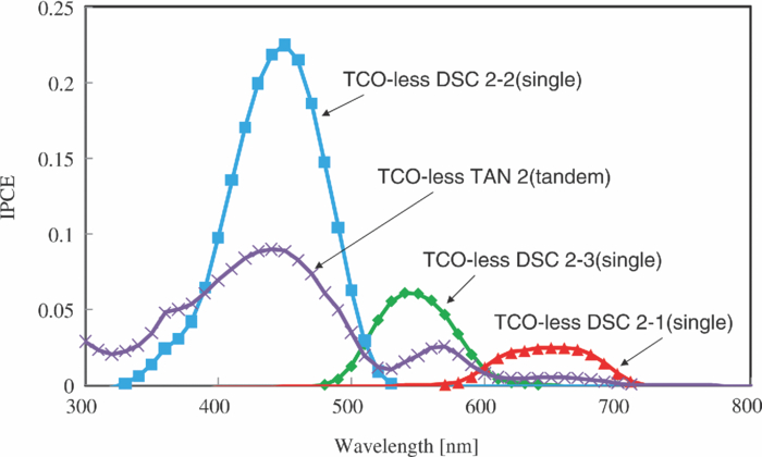
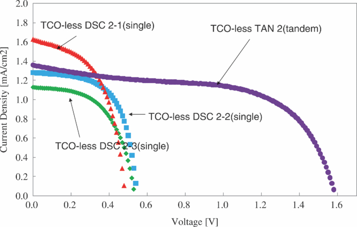
1.IntroductionCertified efficiency of dye-sensitized solar cells (DSCs) with an active area >1 cm2 is 10.4%, which is almost the same as that of an amorphous Si single solar cell.1, 2, 3 However, the efficiency is still lower than those of other solar cells, such as crystal Si solar cells and compound solar cells. One approach to increase efficiencies is to improve light-harvesting properties by using new dyes covering a wide range of wavelengths.4, 5, 6, 7, 8, 9, 10, 11, 12 To use tandem cells is another approach to increase photovoltaic performances. There are several reports on tandem cells where two single cells were merely piled up.13, 14, 15 For example, it has been reported that a photovoltaic tandem cell comprising a DSC as a top cell for high-energy photons and a copper indium gallium selenide thin film as a bottom cell for lower-energy photons produces air mass 1.5 solar to electric conversion efficiencies of >15%.13, 14 A tandem cell consisting of a top cell [F-doped SnO2 (FTO) glass /TiO2 stained by a Ru dye (N719)/electrolyte layer/FTO glasses] and a bottom cell [FTO glass/TiO2 stained by a Ru dye (Black dye)/electrolyte layer/ FTO glasses] has been reported.14, 15 However, these cells are not practical because they need more than three transparent conductive layered glasses and transparent conductive oxide (TCO) layers make up a substantial fraction of the overall device cost. Tandem or hybrid cells having two metal-oxide electrodes in one cell have been reported, where the two metal-oxide layers were stained with different dyes.17, 18, 19 A hybrid cell consisting of a top electrode (FTO glass/TiO2 layer stained with N3)/electrolyte/Pt mesh electrode/electrolyte/a bottom electrode (TiO2 stained with black dye)/FTO glass] has been reported. The Pt electrode is inserted in an electrolyte layer between the top and bottom electrodes. These two titania electrodes were connected in parallel.16 A tandem cell consisting of a top electrode (FTO glass/TiO2 stained by N3) and a bottom electrode (NiO stained by Erythrosin B/FTO glass) has been reported.18, 19 We have also reported a tandem cell consisting of a conventional anode as a top electrode and a flexible nanoporous titania sheet as a bottom electrode.20 The bottom electrode is a self-standing and flexible sheet composed of nanoporous titania layer supported by a protected stainless steel sheet or a glass mesh sheet. During these experiments on tandem cells, we knew that a light-harvesting loss was caused by each layer, such as a TCO layer, and an interlayer between a top and bottom layer. A TCO layer has a large absorption in infrared (IR) area. Therefore, a TCO-less tandem (TCO-less TAN) structure is preferable to a conventional tandem cell structure with a TCO layer when light in IR regions must be photoconverted. In this paper, we propose TCO-less tandem structures and prove that the structure works as tandem cells. 2.Experimental Section2.1.TCO-less Glass Fiber Tandem DSC With Light-Scattering WaveguideFigure 1 shows a glass-fiber-type dye-sensitized solar cell structure and the working principle. The cell consists of a glass fiber/porous TiO2 layer stained with a dye/a porous Ti electrode (anode)/a gel electrolyte sheet/a Ti sheet (counter electrode, cathode). Light is introduced from the glass rod edge and absorbed by a TiO2 layer stained with dyes fabricated on the glass rod. Photogenerated electrons are collected by a porous Ti electrode on a porous TiO2/dye layer. The preparation process of the porous Ti electrode is described in our previous paper.21 Collected electrons are directed to a counter Ti electrode with a Pt layer and are injected into I2 in an electrolyte to form I–. I– species diffuse in an electrolyte layer and give electrons to oxidized dye molecules. The structure is similar to back-contact-type DSCs fabricated on a flat glass substrate reported previously.22, 23, 24 Figure 2 shows a TCO-less glass fiber tandem DSC structure (TCO-less TAN 1). Two cells are placed on a glass fiber and connected in series. A top cell was prepared in the following procedure. TiO2 paste (Ti-nanooxide D - Solaronix, Aubonne, Switzerland) was coated on a glass tube (8 mm o.d., 6.3 mm i.d, 30 mm length), and the glass tube was baked at 450°C for 30 min. The process was repeated to prepare a porous TiO2 electrode with 6 μm thickness. A mixture solution of tetrapod-shaped ZnO (Panatetra WZ-0501 - Panasonic, Matsushita Electric Industrial Co., Ltd., Toyonaka, Osaka, Japan) and P25 - Degussa (Evonik Degussa Corporation, Parsippany, NJ, USA) in ethyl alcohol was sprayed on the porous TiO2 layer, where the tetrapod-shaped ZnO acts as a template of nanoholes.21 The glass tube was baked again at 450°C for 30 min. Ti was sputtered on the layer by rotating the glass tube [SH-250-T04 (Sputter–ULVAC, Kanagawa, Japan) 200 W, 6.6 × 10⁻⁴ Pa]. After that, ZnO crystals were removed by dipping the tube into a solution consisting of 40% acetylacetone and 60% methanol to make a porous Ti electrode. The size of a ZnO crystal is from 1 to 10 μm. At least one of the four hands of a ZnO crystal sticks out from a sputtered Ti film (500 nm thick). The ZnO crystal was washed away from portions sticking out from a sputtered Ti film. Then, the substrate was dipped in a dye 2 (Fig. 3) solution [a mixture solution of dye 2 (0.25 mM) and chenodeoxycholic acid (37.5 mM) in ethanol] to stain the porous TiO2 layer. Then, the substrate was covered with a porous poly(tetrafluoroethylene) film [(PTFE), Advantec, Tokyo, Japan, 0.1-μm pore size, 35 μm thick], followed by a Ti sheet (Nilaco, Tokyo, Japan, 50 μm thick). A bottom cell was fabricated in the same way by using dye 1 (Fig. 3). A mixture of dye 1 (0,25 mM) and chenodeoxycholic acid (37.5 mM) in ethanol was used for the dye staining. After that, an electrolyte solution (Electrolyte C) consisting of 500 mM LiI, 50 mM I2, 580 mM t-butylpyridine, 600 mM ethylmethylimidazolium dicyanoimide in acetonitrile was injected into the porous PTFE film. Fig. 2TCO-less glass-fiber tandem DSC structure (TCO-less TAN 1): (A) Polystyrene dispersion (132 nm diam) in water, (B) polystyrene dispersion (592 nm diam) in water, (C) porous titania stained with dye 2, (D) porous titania stained with dye 1, (E) porous Ti electrode, (F) Ti sheet (counter electrode), (C + E) or (D + E) porous titania sheet. 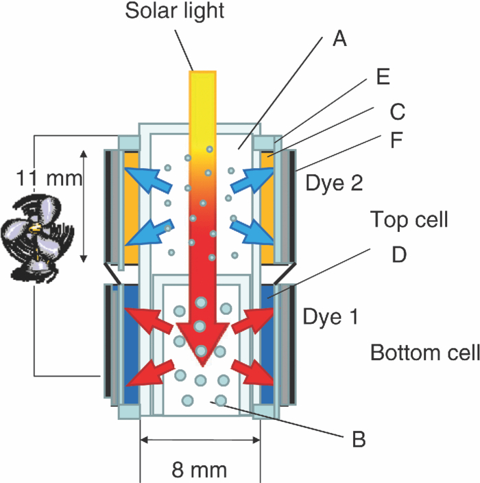 The absolute photovoltaic performances for these two model dyes were not high. These two dyes were selected because visible-light absorption of dye 2 does not overlap with that of dye 1. This simplified the analyses of tandem performances. Finally, these two cells were connected in series, as shown in Fig. 2. Light-splitting units consist of two compartments (a glass tube 2.8 mm o.d., 6.3 mm i.d., 11 mm length and a glass tube 1: 6 mm o.d., 4.8 mm i.d., 11 mm length) in which polystyrene particles with 132 and 592 nm diam (Seradyn Inc., Indianapolis, IN, USA 10% dispersion in water) were dispersed. A commercially available polystyrene dispersion in water (132 nm diam) were diluted 1000 times with water and the latter dispersion (592 nm diam) was diluted with water 200 times. The two light-splitting units were placed into the right positions of a glass tube where two TCO-less DSCs were placed, as shown in Fig. 2. 2.2.TCO-Less Pillar Tandem DSC with Light-Splitting Waveguide (TCO-less TAN 2)A TCO-less TAN 2 is composed of TCO-less DSCs and light-splitting waveguide consisting of dichroic mirrors (Fig. 4). Flat TCO-less DSCs (TCO-less DSCs 2-1, 2-2, and 2-3) were prepared by coating titania paste (Titania D, Solaronix) on a stainless mesh sheet (25-μm-diam stainless wire, 40-μm sheet thickness, 25-μm space between the wire, product of ASADA, Osaka, Japan). The stainless wire was protected with a TiOx thin layer, where x changed from 0 to 2 gradually from the position contacting stainless wire surface to that contacting the surface of a porous titania layer.25 This TiOx thin layer effectively blocked charge recombination between electrons in the stainless steel surface and iodine in an electrolyte.25 The TiOx layer was fabricated by Ti sputtering (ULVAC model SH-250) using a Ti target by a method described in our previous report.25 The electrode was baked at 450°C for 1 h. Three electrodes were stained by dipping these substrates into solutions of dyes shown in Fig. 5, respectively. The thickness of the porous titania layers was 6 μm. A glass (a cover glass for a microscope, 1 mm thick), a porous titania sheet stained with a dye, a gel electrolyte sheet, and a counter electrode (Pt-sputtered Ti sheet, NILAKO, t:100 μm) were merely piled up to prepare TCO-less DSCs 2-1, 2-2, and 2-3. Model dyes 1, 2, and 3 (Fig. 5) were not high-efficiency dye molecules. They were selected because their visible absorptions did not overlap each other. A gel electrolyte sheet was prepared by infiltrating Electrolyte C in a porous polymer sheet, which was described in Sec. 2.1. Three cells were connected in series on a wall of a specially designed square glass tube, as shown in Fig. 6. A 5 × 5 mm mask was placed on each DSC. Dichroic mirrors were placed in a glass tube, as shown in Fig. 4, in a square glass tube. Photovoltaic performances were monitored with a simulator KHP-1 (Bunko Keiki, Tokyo, Japan) equipped with a xenon lamp (XLS-150A). The exposure light was adjusted to be AM1.5 (100 mW/cm2). The solar simulator spectra and power were adjusted using an Eiko Seiki solar simulator spectroradiometer LS-100. Exposure power was also corrected with an amorphous Si photodetector (Bunko-Keiki BS-520 S/N 007), which has visible-light sensitivity similar to that of DSC. After the cell fabrication, the cell area was precisely recalculated using the obtaining photograph image. A mask was placed on the inlet of light of fiber or pillar glasses. Short-circuit current (Jsc) was calculated by using this area. Spectra of split light were monitored by a solar simulator spectroradiometer LS-100 (Eiko Seiki, Tokyo, Japan). Dyes 1, 2, and, 3 were synthesized in our lab, according to a method reported in our previous papers.26, 27 3.Results and Discussion3.1.TCO-less Fiber Tandem DSC with Light-Scattering Waveguide (TCO-less TAN 1)Figure 7 shows scattered light spectra from polystyrene particles of a top and bottom cells in Fig. 2. A top waveguide consisted of 132-nm-diam polystyrene particles in water mainly scattered light in the range of 400–600 nm, and the scattered light was visibly blue, as shown in an inset of Fig. 7. A bottom waveguide consisted of 592-nm-diam polystyrene particles of scattered light of wavelength of >400 nm, and the scattered light was visibly white. Figure 8 shows an incident photon-to-current efficiency (IPCE) curve for a TCO-less TAN 1 shown in Fig. 2. Two peaks were observed at around 430 and 650 nm, which correspond to dye 2 (λmax: 429 nm) and dye 1 (λmax: 646 nm), respectively, clearly demonstrated that two electrodes generated electrons. Figure 9 shows photovoltaic performances for TCO-less TAN 1 and corresponding single cells consisting of top and bottom cell structures. Open-circuit voltage (Voc) of TCO-less TAN 1 was 1.15 V, which was the same as the sum of 0.59 V for a top single cell and 0.56 V for a bottom single cell. These results on IPCE curves and I–V curves show that a TCO-less TAN 1 structure worked as a tandem cell. Short-circuit current (Jsc) of a flat TCO-less DSC stained by dyes 1 or 2 was about 5–7 mA/cm2 when solar light was introduced vertically to the flat TCO-less DSC (normal configuration). Low Jsc of 0.8–1.0 mA/cm2 in this TCO-less DSC is explained by low light-scattering properties of polystyrene particles. A waveguide structure in which light is effectively scattered is needed to obtain high-efficiency cells. Precise photovoltaic performances were as follows: Top single cell (efficiency 0.37%, FF 0.66, Voc 0.59 V, Jsc 0.96 mA/cm2), bottom single cell (efficiency 0.3%, FF 0.65, Voc 0.56 V, Jsc 0.84 mA/cm2), and TCO-less TAN 1 (efficiency 0.69%, FF 0.66, Voc 1.15 V, Jsc 0.92 mA/cm2). 3.2.Photovoltaic Performances of TCO-less TAN 2 with Dichroic MirrorsFigure 10 shows split light spectra from dichroic mirrors 1, 2, 3, and a whole light spectrum from a solar simulator. Dichroic mirrors 2, 3, and 1 split lights from 350 to 520 nm, from 480 to 600 nm, and >550 nm, respectively. These dichroic mirrors were coupled with TCO-less DSCs stained by dyes 2, 3, and 1, whose absorption spectra are shown in Fig. 5. Dye 2 (350–450 nm) absorbs light split from a dichroic mirror 2 (light from 350 to 520 nm). Dye 3 (420–550 nm) absorbs light split from a dichroic mirror 3 (light from 480 to 600 nm). Dye 1 (550–670 nm) absorbs light split from a dichroic mirror 1 (light longer than 550 nm). IPCE curves for TCO-less TAN 2 had three peaks of 450, 550, and 650 nm, which correspond to those of single cells of TCO-less DSC 2-2 stained with dye 2, TCO-less DSC 2-3 stained with dye 3, and TCO-less DSC 2-1 stained with dye 1, as shown in Fig. 11. These three IPCE peaks demonstrate that three TCO-less DSCs (TCO-less DSCs 2-2, 2-3, and 2-1, shown in Fig. 6) generated electrons. Photovoltaic performances for these cells were as follows: TCO-less DSC 2-1: efficiency 0.42%, FF 0.54, Voc 0.49 V, Jsc 1.63 mA/cm2, TCO-less DSC 2-2: efficiency 0.43%, FF 0.61, Voc 0.55 V, Jsc 1.28 mA/cm2; TCO-less DSC 2-3: efficiency 0.33%, FF 0.55, Voc 0.53 V, Jsc 1.13 mA/cm2; and TCO-less TAN 2: efficiency 1.25%, FF 0.58, Voc 1.59 V, Jsc 1.36 mA/cm2. Voc of a TCO-less TAN 2 was 1.59 V, which was almost the sum of corresponding single cells, as shown in Fig. 12. These results show that TCO-less DSC TAN 2 structure works as a three-connected tandem cell. Jsc of TCO-less DSC 2-1 was a little higher than that of TCO-less TAN 2. Because of reproducibility of cell alignment position on the photovoltaic measurement in a solar simulator, Jsc has some experimental errors. However, the experimental errors do not deny the fact that TCO-less TAN 2 showed tandem performance because Voc is closely related to the demonstration of tandem properties. Fig. 10Split light spectra from dichroic mirrors 1, 2, 3, and the whole light spectrum for solar simulator. 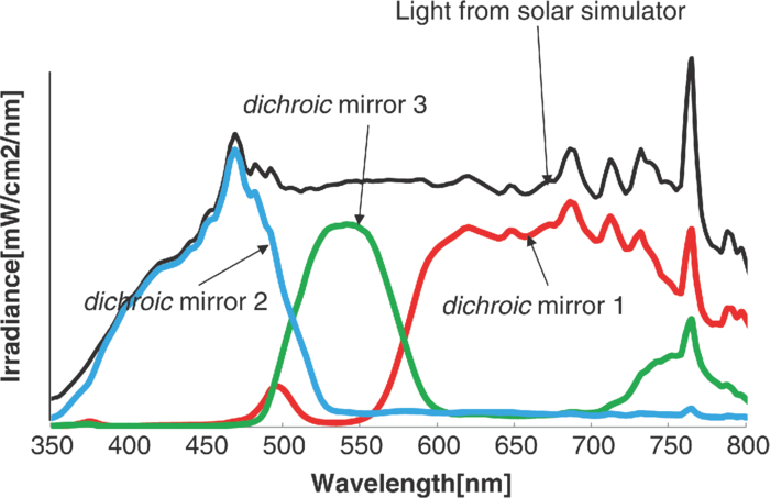 4.ConclusionTCO-less tandem DSC cells consisting of TCO-less DSCs and light splitting waveguides were proposed and proved to work as tandem cells. TCO-less TAN 1 was a rod (or fiber) tandem (two-tandem structure) composed of two TCO-less DSCs and a waveguide consisting of polystyrene dispersions with different diameters in water. TCO-less TAN 2 (three-tandem structure) was a pillar structure consisting of three dichroic mirrors in a waveguide as light-splitting structures. These results on IPCE curves and I–V curves demonstrated that these TCO-less tandem structures worked as tandem cells. Even though these actual efficiencies are low, the fundamental functions as tandem cells were proved. To obtain high efficiency (>15%), two items are needed, namely, a waveguide structure with efficient light-splitting properties and high-efficiency dyes that work in the range of near-infrared and infrared regions. ReferencesB. O’Regan and M. Grätzel,
“A low-cost, high-efficiency solar cell based on dye-sensitized colloidal TiO2 films,”
Nature, 353 737
–740
(1991). http://dx.doi.org/10.1038/353737a0 Google Scholar
Y. Chiba, A. Islam, Y. Watanabe, R. Komiya, N. Koide, and L. Han,
“Dye-Sensitized Solar Cells with Conversion Efficiency of 11.1%,”
Jpn. J. Appl. Phys., 45 L638
–L640
(2006). http://dx.doi.org/10.1143/JJAP.45.L638 Google Scholar
M. A. Green, K. Emery, D. L. King, Y. Hishikawa, and W. Warta,
“Solar cell efficiency tables (version 36),”
Prog. Photovolt: Res. Appl., 18 346
–352
(2010). http://dx.doi.org/10.1002/pip.1021 Google Scholar
M. K. Nazeeruddin, A. Kay, I. Rodicio, R. Humphry-Baker, E. Muller, P. Liska, N. Vlachopoulos, and M. Grätzel,
“Conversion of light to electricity by cis-X2bis(2,2′-bipyridyl-4,4′-dicarboxylate)ruthenium(II) charge-transfer sensitizers (X = Cl-, Br-, I-, CN-, and SCN-) on nanocrystalline titanium dioxide electrodes,”
J. Am. Chem. Soc., 115 6382
–6390
(1993). http://dx.doi.org/10.1021/ja00067a063 Google Scholar
T. Renouard, R.-A. Fallahpour, M. K. Nazeerudin, R. Humphry-Baker, S. I. Gorelsky, A. B. P. Lever, and M. Grätzel,
“Novel ruthenium sensitizers containing functionalized hybrid tetradentate ligands: Synthesis, characterization, and INDO/S analysis,”
Inorg. Chem., 41 367
–378
(2002). http://dx.doi.org/10.1021/ic010512u Google Scholar
R. Amadelli, R. Argazzi, C. A. Bignozzi, and F. Scandola,
“Design of antenna-sensitizer polynuclear complexes. Sensitization of titanium dioxide with [Ru(bpy)2(CN)2]2Ru(bpy(COO)2)22,”
J. Am. Chem. Soc., 112 7099
–7103
(1990). http://dx.doi.org/10.1021/ja00176a003 Google Scholar
Z.-S. Wang, C.-H. Huang, B.-W. Zhang, Y.-Y. Hou, P.-H. Xie, H.-J. Qian, and K. Ibrahim,
“Highly efficient charge transfer from a trans-ruthenium bipyridine complex to nanocrystalline TiO2 particles,”
New J. Chem., 24 567
–568
(2000). http://dx.doi.org/10.1039/b004078i Google Scholar
M. K. Nazeeruddin, P. Pechy, T. Renouard, S. M. Zakeeruddin, R. Humphry-Baker, P. Comte, P. Liska, L. Cevey, E. Costa, V. Shklover, L. Spiccia, G. B. Deacon, C. A. Bignozzi, and M. Grätzel,
“Engineering of efficient panchromatic sensitizers for nanocrystalline TiO2-based solar cells,”
J. Am. Chem. Soc., 123 1613
–1624
(2001). http://dx.doi.org/10.1021/ja003299u Google Scholar
Z.-S. Wang, T. Yamaguchi, H. Sugihara, and H. Arakawa,
“Significant efficiency improvement of the black dye-sensitized solar cell through protonation of TiO2 films,”
Langmuir, 21 4272
–4276
(2005). http://dx.doi.org/10.1021/la050134w Google Scholar
M. Gratzel,
“Conversion of sunlight to electric power by nanocrystalline dye-sensitized solar cells,”
J. Photochem. Photobiol. A, 164 3
–14
(2004). http://dx.doi.org/10.1016/j.jphotochem.2004.02.023 Google Scholar
P. Wang, S. M. Zakeeruddin, P. Comte, R. Charvet, R. Humphry-Baker, and M. Grätzel,
“Enhance the performance of dye-sensitized solar cells by co-grafting amphiphilic sensitizer and hexadecylmalonic acid on TiO2 nanocrystals,”
J. Phys. Chem. B, 107 14336
–14341
(2003). http://dx.doi.org/10.1021/jp0365965 Google Scholar
F. Gao, Y. Wang, J. Zhang, D. Shi, M. Wang, R. H.-Baker, P. Wang, S. M. Zakeeruddin, and M. Grätzel,
“A new heteroleptic ruthenium sensitizer enhances the absorptivity of mesoporous titania film for a high efficiency dye-sensitized solar cell,”
Chem. Commun., 2008 2635
–2637
(2008). http://dx.doi.org/10.1039/b802909a Google Scholar
P. Liska, K. R. Tampi, M. Graetzel, D. Bremaud, D. Rudmann, H. M. Upadhyaya, and A. N. Tiwari,
“Nanocrystalline dye-sensitized solar cell/copper indium gallium selenide thin-film tandem showing greater than 15% conversion efficiency,”
Appl. Phys. Lett., 88 203103
(2006). http://dx.doi.org/10.1063/1.2203965 Google Scholar
W. Kubo, A. Sakamoto, T. Kitamura, Y. Wada, and S. Yanagida,
“Dye-sensitized solar cells: improvement of spectral response by tandem structure,”
J. Photochem. Photobiol. A, 164 33
–39
(2004). http://dx.doi.org/10.1016/j.jphotochem.2004.01.024 Google Scholar
M. Dürr, A. Bamedi, A. Yasuda, and G. Nelles,
“Tandem dye-sensitized solar cell for improved power conversion efficiencies,”
Appl. Phys. Lett., 84 3397
(2004). http://dx.doi.org/10.1063/1.1723685 Google Scholar
M. Murayama and T. Mori,
“Dye-sensitized solar cell using novel tandem cell structure,”
J. Phys. D, 40 1664
–1668
(2007). http://dx.doi.org/10.1088/0022-3727/40/6/014 Google Scholar
F. Inakazu, Y. Noma, Y. Ogomi, and S. Hayase,
“Dye-sensitized solar cells consisting of dye-bilayer structure stained with two dyes for harvesting light of wide range of wavelength,”
Appl. Phys. Lett., 93 093304
–093304-3
(2008). http://dx.doi.org/10.1063/1.2976677 Google Scholar
J. He, H. Lindström, A. Hagfeldt, and S.-E. Lindquist,
“Dye-sensitized nanostructured tandem cell-first demonstrated cell with a dye-sensitized photocathode,”
Sol. Energy Mater. Sol. Cells, 62 265
–273
(2000). http://dx.doi.org/10.1016/S0927-0248(99)00168-3 Google Scholar
F. Vera, R. Schrebler, E. Muñoz, C. Suarez, P. Cury, H. Gómez, R. Córdova, R. E. Marotti, and E. A. Dalchiele,
“Preparation and characterization of Eosin B- and Erythrosin J-sensitized nanostructured NiO thin film photocathodes,”
Thin Solid Films, 490 182
–188
(2005). http://dx.doi.org/10.1016/j.tsf.2005.04.052 Google Scholar
K. Uzaki, S. S. Pandey, Y. Ogimi, and S. Hayase,
“Tandem dye-sensitized solar cells consisting of nanoporous titania sheet,”
Jpn. J. Appl. Phys., 49 082301
(2010). http://dx.doi.org/10.1143/JJAP.49.082301 Google Scholar
Y. Yoshida, S. S. Pandey, K. Uzaki, S. Hayase, M. Kono, and Y. Yamaguchi,
“Transparent conductive oxide layer-less dye-sensitized solar cells consisting of floating electrode with gradient TiOx blocking layer,”
Appl. Phys. Lett., 94 093301
(2009). http://dx.doi.org/10.1063/1.3089845 Google Scholar
J. M. Kroon, N. J. Bakker, H. J. P. Smit, P. Liska, K. R. Thampi, P. Wang, S. M. Zakeeruddin, M. Graetzel, A. Hinsch, S. Hore, U. Wurfel, R. Sastrawan, J. R. Durrant, E. Palomares, H. Pettersson, T. Gruszecki, J. Walter, K. Skupien, and G. E. Tulloch,
“Nanocrystalline dye-sensitized solar cells having maximum performance,”
Prog. Photovol., 15 1
–18
(2007). http://dx.doi.org/10.1002/pip.707 Google Scholar
N. Fuke, A. Fukui, Y. Chiba, R. Komiya, R. Hamanaka, and L. Han,
“Back contact dye-sensitized solar cells,”
Jpn. J. Appl. Phys., 46 L420
–L422
(2007). http://dx.doi.org/10.1143/JJAP.46.L420 Google Scholar
Y. Kashiwa, Y. Yoshida, and S. Hayase,
“All-metal-electrode-type dye sensitized solar cells (transparent conductive oxide-less dye sensitized solar cell) consisting of thick and porous Ti electrode with straight pores,”
Appl. Phys. Lett., 92 033308
(2008). http://dx.doi.org/10.1063/1.2837633 Google Scholar
Y. Yoshida, Y. Noma
Y. Kashiwa, S. Kojima, T. Katoh, and S. Hayase,
“I2-Resistant TiOx/Ag collector fabricated by arc plasma deposition for dye-sensitized solar cells,”
Jpn. J. Appl. Phys., 47 6484
–6487
(2008). http://dx.doi.org/10.1143/JJAP.47.6484 Google Scholar
S. S. Pandey, T. Inoue, N. Fujikawa, Y. Yamaguchi, and S. Hayase,
“Substituent effect in direct ring functionalized squaraine dyes on near infra-red sensitization of nanocrystalline TiO2 for molecular photovoltaics,”
J. Photochem. Photobio. A, 214 269
–275
(2010). http://dx.doi.org/10.1016/j.jphotochem.2010.07.010 Google Scholar
T. Inoue, S. S. Pandey, N. Fujikawa, Y. Yamaguchi, and S. Hayase,
“Synthesis and characterization of squaric acid based NIR dyes for their application towards dye-sensitized solar cells,”
J. Photochem. Photobio. A, 213 23
–29
(2010). http://dx.doi.org/10.1016/j.jphotochem.2010.04.015 Google Scholar
|