|
|
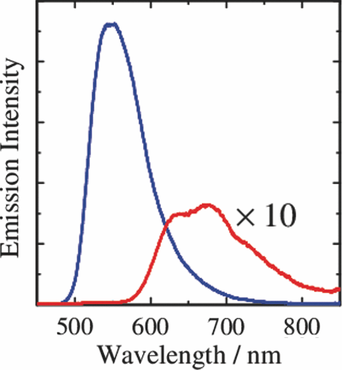
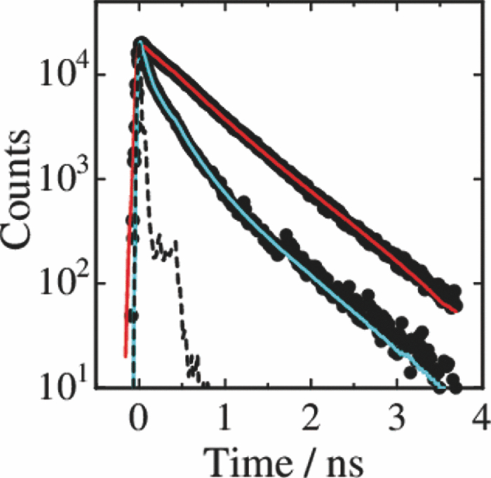
1.IntroductionPolymer solar cells are typically based on a bicontinuous blend of donor and acceptor materials, and can be classified into two types in terms of acceptor materials, that is, polymer/fullerene solar cells based on a blend of a conjugated polymer and a fullerene derivative such as [6,6]-phenyl-C61 butyric acid methyl ester [PBCM, Fig. 1] and polymer/polymer solar cells based on a blend of a donor polymer and an acceptor polymer. In 1995, two pioneer papers were independently published for these polymer solar cells.1, 2 The power conversion efficiency (PCE) of polymer/fullerene solar cells has been steadily improved in decades and most recently exceeds 7 to 8%.3, 4, 5 In contrast, the PCE of polymer/polymer solar cells still remains at ∼2%.6, 7 In other words, there is a significant difference in the device performance between them. Fig. 1Chemical structures of donor and acceptor materials employed in this study: (a) P3HT, (b) F8BT, (c) PCBM, and (d) the energy level diagram of these materials. The energy levels are taken from Refs. 6 and 13. 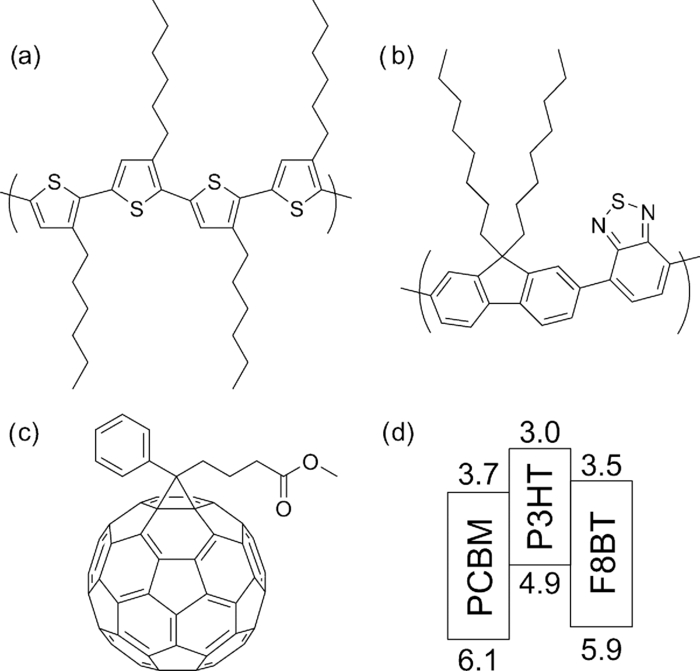 The polymer/fullerene solar cell based on poly 3-hexylthiophene (P3HT) and PCBM has been most widely studied in recent years, exhibiting reproducible PCE at around 4 to 5% with relatively high external quantum efficiency (>80%) and high fill factor (∼0.7).8, 9, 10, 11, 12 These device parameters are still the highest in organic solar cells. In contrast, the polymer/polymer solar cell based on [P3HT, Fig. 1] and poly(9,9-dioctylfluorene-alt-benzothiadiazole) (F8BT) exhibits poor device performance with PCE of less than 0.2%.13, 14 The major difference between them is in the acceptor material: the PCBM molecule is employed in the polymer/fullerene solar cell and the [F8BT, Fig. 1] polymer in the polymer/polymer solar cell. Both acceptor materials are n-type semiconductors with relatively high electron mobility (≥10−4 cm2 V−1 s−1).13, 15 In blend films with P3HT, as shown in Fig. 1, there is a large LUMO–LUMO offset of more than 0.5 eV at the heterojunction, which is generally considered to be enough for excitons to be dissociated into free carriers.16 Therefore, these polymer solar cells should exhibit similar device performance in terms of thermodynamics. However, this is not the case as mentioned above. Previously we reported that there are two pathways for the charge generation in P3HT/PCBM blend films.17 Half of the polarons are promptly generated immediately after the laser excitation on a time scale of <0.1 ps, and the remaining half on a time scale of ∼10 ps. The prompt polaron formation is ascribed to the charge generation from excitons generated near the interface without diffusion. The delayed polaron formation is ascribed to the charge generation after exciton diffusion into the interface. Large polaron bands are observed even on a time scale of microseconds, suggesting that both processes are so efficient that most of the polarons can be dissociated into free carriers in this blend film. Herein we measure transient absorption spectra of P3HT/F8BT blend films to compare the charge generation dynamics with that of P3HT/PCBM blend films. We discuss the origin of the significant difference in the device performance between P3HT/F8BT and P3HT/PCBM solar cells (see Fig. 1). 2.Experimental2.1.MaterialsPristine films of P3HT (Aldrich, head-to-tail >98%, Mw = 50,300, Mw/Mn = 2.2) and F8BT (Aldrich, Mw = 19,000, Mw/Mn = 2.7) were prepared onto glass substrates by spin-coating from a chlorobenzene (Aldrich) and a chloroform (Dojindo, Spectrosol) solution, respectively. Blend films of P3HT/F8BT were also prepared onto glass substrates by spin-coating from a chloroform solution of P3HT and F8BT (1:1 by weight) at a concentration of ∼20 mg mL−1. Before spin-coating, the blend solution was stirred at room temperature overnight. The blend films were annealed at 170°C for 60 min. The film thickness was approximately 150 nm. The substrates employed were cleaned by ultrasonic treatment in toluene, acetone, and ethanol for 15 min, and furthermore treated with a UV–O3 cleaner (Nippon Laser & Electronics Lab., NL-UV253S) for 30 min before spin-coating. 2.2.MeasurementsUV–visible absorption and photoluminescence spectra of films were measured with a UV–visible spectrophotometer (Hitachi, U-3500) and a fluorescence spectrophotometer (Hitachi, F-4500) equipped with a red-sensitive photomultiplier (Hamamatsu, R928F), respectively. Transient absorption data were collected with a pump and probe femtosecond transient absorption spectroscopy system and with a highly sensitive microsecond transient absorption system.18 The pump and probe femtosecond transient absorption spectroscopy system consists of a transient absorption spectrometer (Ultrafast Systems, Helios) and a regenerative amplified Ti:sapphire laser (Spectra-Physics, Hurricane). The amplified Ti:sapphire laser provided 800-nm fundamental pulses at a repetition rate of 1 kHz with an energy of 0.8 mJ and a pulse width of 100 fs (FWHM), which were split into two optical beams with a beam splitter to generate pump and probe pulses. One fundamental beam was converted into pump pulses at 400 nm with a second harmonic generator (Spectra-Physics, TP-F). The other fundamental beam was converted into white light continuum pulses employed as probe pulses over the wide wavelength from 400 to 1700 nm. The pump pulses were modulated mechanically with a repetition rate of 100 Hz for visible and 500 Hz for near-IR measurements. The temporal evolution of the probe intensity was recorded with a Si CCD-array photodetector (Ocean Optics, S2000) for the visible measurement and with an InGaAs digital line scan camera (Sensors Unlimited, SU-LDV) for the near-IR measurement. Transient absorption spectra and decays were collected in the time range of −5 ps to 3 ns. Typically, 200 to 1000 laser shots were averaged on each delay time to obtain a detectable absorbance change before and after the laser excitation (ΔOD) as small as 10−4 to 10−3 depending on the monitor wavelength. In order to cancel out orientation effects on the dynamics, the polarization direction of the linearly polarized probe pulse was set at a magic angle of 54.7 deg with respect to that of the pump pulse. The sample films were sealed in a quartz cuvette purged with Ar for 30 min. Note that the transient absorption spectra and dynamics were highly reproducible even after the laser excitation. In other words, the laser irradiation had negligible effects on the morphology change for the films. Photoluminescence decay was measured by the time-correlated single photon counting method.19 The excitation pulses at 400 nm were created by second harmonic generation from a mode-locked Ti:sapphire laser (Spectra-Physics, Tsunami 3950) that was pumped with an Ar+ laser (Spectra-Physics, BeamLok 2060). The photoluminescence from the sample films was detected by a microchannel plate photomultiplier tube (MCP; Hamamatsu Photonics, R3809) with a cut-off filter for eliminating the excitation pulses. The MCP signal was sent to a constant fraction discriminator (Ortec, model 583) and served as the start pulse for a time-to-amplitude converter (TAC; Ortec, model 457). The residual second harmonic pulse was detected by a photodiode (Antel Optronics, AR-S2) to provide the stop pulse for the TAC converter through a 100-MHz discriminator (Ortec, model 436). The TAC signal was transferred to a multichannel analyzer (Laboratory Equipment Corporation, 2100C/MCA). The total instrument response function was an FWHM of ca. 60 ps. A weak excitation power (∼nJ cm−2) was used in the measurement to prevent singlet exciton–exciton annihilation. 3.Results3.1.Absorption and Emission SpectraThe black line in Fig. 2 shows the absorption spectrum of a blend film of P3HT and F8BT. Considering the absorption coefficient and the volume fraction of P3HT and F8BT in the blend, we can obtain the absorption spectra of each component. As shown in Fig. 2, F8BT absorption is dominant in the wavelength range shorter than 470 nm and P3HT absorption is dominant in the wavelength range longer than 470 nm. At an excitation wavelength of 400 nm, 60% of photons are absorbed by F8BT and the remaining 40% of photons are absorbed by P3HT. At wavelengths longer than 550 nm, P3HT can be selectively excited. An absorption shoulder, which is indicative of P3HT crystallization, was observed at around 600 nm but is much smaller than that observed for P3HT pristine films, suggesting that the crystallinity of P3HT is not as high in the blend as in the P3HT pristine film. Fig. 2Absorption spectrum of a P3HT/F8BT blend film (top, black line). The red and blue lines represent absorption spectra of each component in the blend film: P3HT (middle, red line) and F8BT (bottom, blue line). 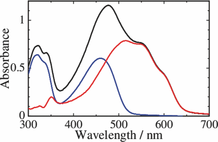 Figure 3 shows the emission spectra of an F8BT pristine and a P3HT/F8BT blend film excited at 400 nm. As shown in Fig. 3, the F8BT pristine film exhibited a large emission band at 550 nm. In contrast, no F8BT emission was observed for the P3HT/F8BT blend film even though F8BT was dominantly excited at 400 nm. Instead, small emission bands ascribed to the P3HT emission were observed at around 600 to 700 nm. This significant quenching of the F8BT emission suggests efficient energy transfer or electron transfer from F8BT to P3HT. On the other hand, the small P3HT emission is probably ascribed to the relatively low quantum efficiency of P3HT singlet excitons generated by the energy transfer from F8BT and the direct excitation of P3HT or to the quenching by electron transfer between F8BT and P3HT. 3.2.Time-Resolved Emission DecayIn order to address the quenching mechanism, we measured time-resolved emission decay of P3HT pristine and P3HT/F8BT blend films. As shown in Fig. 4, the emission of the P3HT pristine film decayed almost monoexponentially. Indeed, the decay dynamics was fitted with a double-exponential function with two close time constants of 406 and 762 ps. In contrast, the emission of the P3HT/F8BT blend decayed much faster with a major short time constant of 40 ps and minor long constants of 222 and 755 ps. The short lifetime observed for the blend indicates that the small emission of P3HT is partly due to the electron transfer from P3HT to F8BT, which is consistent with the LUMO–LUMO offset of more than 0.5 eV. On the other hand, no distinct rise of P3HT was observed in the time-resolved emission decay. This suggests the absence of energy transfer from F8BT to P3HT or prompt energy transfer beyond the time resolution. The fitting parameters are summarized in Table 1. Table 1Fitting parameters for the time-resolved emission decay.
3.3.Transient AbsorptionTo study the decay dynamics on a picosecond timescale, we measured the transient absorption spectra of P3HT/F8BT blend films excited at 400 nm. As shown in Fig. 5, two absorption bands were observed at around 1000 and 1250 nm immediately after the laser excitation. The absorption at 1000 nm is ascribed to F8BT singlet excitons because it is consistent with that of F8BT pristine films observed immediately after the laser excitation. The absorption at 1250 nm is ascribable to P3HT singlet excitons as reported previously.19 The F8BT singlet exciton band at 1000 nm rapidly decayed in a picosecond. On the other hand, the P3HT singlet exciton band increased up to 1 ps after the laser excitation, consequently became dominant, and then decayed on a time scale of tens of picoseconds. The decay dynamics of the P3HT singlet exciton band was strongly dependent on the excitation intensity, suggesting singlet exciton–exciton annihilation. After 100 ps, P3HT singlet excitons disappeared and instead a small absorption band was observed at around 1000 nm, which is ascribed to P3HT polarons as reported previously.17, 19 This band was still observed even on a microsecond timescale although the absorbance was less than 10−4, suggesting that only a small part of polarons can be dissociated into free carriers. Fig. 5Transient absorption spectra of P3HT/F8BT films excited at 400 nm: (a) measured at 0, 1, 10, 100, 1000 ps, and (b) 0.8, 1, 2, 5, 10 μs from top to bottom in each panel. The ΔOD in the y axis represents the absorbance change before and after the laser excitation, which is multiplied by a factor of (a) 103 and (b) 106. The excitation intensity was 30 μJ cm−2. 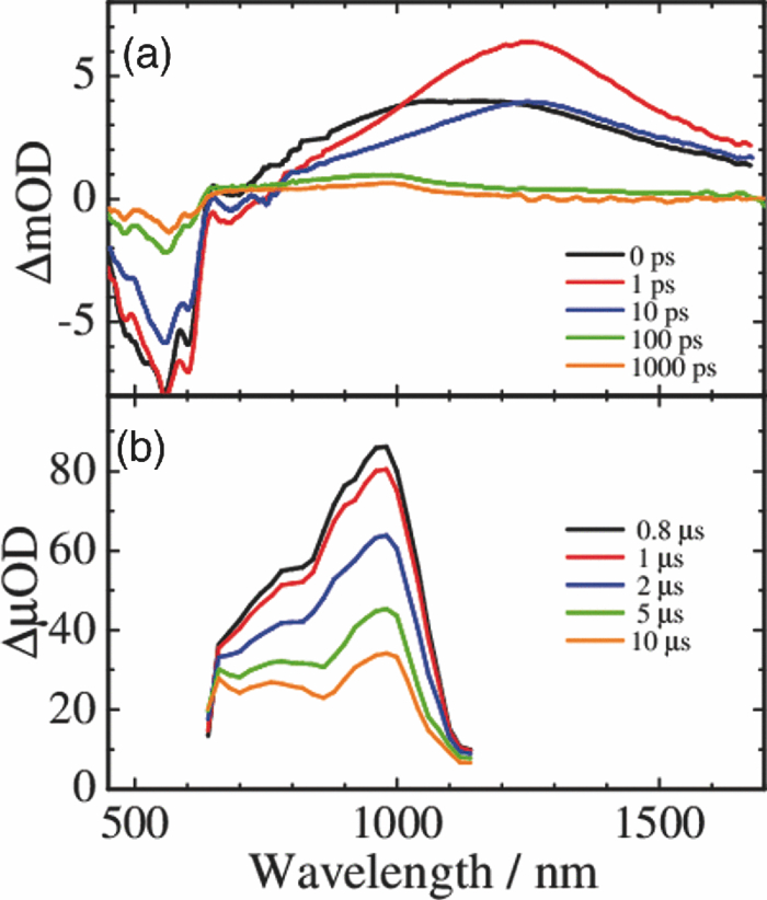 4.Discussion4.1.Energy TransferTo discuss the significant quenching of the F8BT emission in the blend film, we analyzed the decay dynamics of F8BT singlet excitons in detail. The transient absorption spectra in a picosecond was well reproduced by a sum of the S–S absorption spectrum observed for each pristine film of F8BT and P3HT, suggesting that the major transient species are F8BT and P3HT singlet excitons in the time domain of <1 ps. On the basis of such a spectral simulation, the decay dynamics of each transient species can be obtained as shown in Fig. 6. The F8BT singlet exciton decayed monoexponentially with a time constant of ∼0.3 ps. On the other hand, ∼40% of P3HT singlet excitons were promptly generated immediately after the laser excitation and the other ∼60% of P3HT singlet excitons were generated with a rise constant of ∼0.3 ps. The former exciton generation is ascribed to the direct excitation of P3HT at 400 nm because P3HT can absorb 40% of the photons at 400 nm. The latter is ascribed to the energy transfer from F8BT singlet excitons because the P3HT rise is consistent with the F8BT decay constant. The rapid energy transfer suggests that all F8BT singlet excitons are efficiently transferred into P3HT domains without exciton diffusion in this blend film. In other words, there are no large pure domains in the blend: F8BT is molecularly dispersed in P3HT domains and/or P3HT is dispersed in F8BT rich domains. This is probably because chloroform is so rapidly evaporated that blend films are solidated before the phase separation. On the basis of the point dipoles approximation of the Förster theory, such rapid energy transfer is possible at a separation distance of ∼0.9 nm between F8BT and P3HT. Consequently, at least 60% of P3HT singlet excitons are located near the interface of P3HT/F8BT because of the efficient energy transfer from F8BT. This would be beneficial for the subsequent charge separation. In Sec. 4.2, we will discuss the charge generation dynamics. Fig. 6Time evolution of F8BT singlet excitons (decay, red circles) and P3HT singlet excitons (rise, blue circles) extracted from Fig. 5 by spectral simulation. The rise and decay curves are fitted with the following equation: ΔODR = 0.45 + 0.55[1 − exp(−t/τR)] and ΔODD = exp(−t/τD), (τR = τD = 0.3 ps). 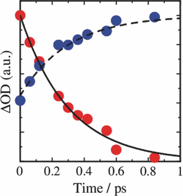 4.2.Charge Generation DynamicsAs mentioned above, all the excitation energy is finally converted to P3HT singlet excitons independently of the excitation wavelength. Here, we focus on the rise and decay dynamics of P3HT polarons and P3HT singlet excitons on a time scale of tens of picoseconds to discuss the charge generation dynamics in the blend film. To analyze the spectral change shown in Fig. 5, we need spectral templates for P3HT singlet exciton and P3HT polaron. The spectrum at 1 ps can be employed as a spectral template for the P3HT singlet exciton because F8BT singlet excitons completely disappear at 1 ps as mentioned above. Indeed, this is in agreement with the S–S absorption observed for P3HT pristine films.19 Similarly, the spectrum at 1 ns can be employed as a spectral template for P3HT polarons because P3HT singlet excitons completely disappear at 1 ns as shown in Fig. 5 and is in agreement with polaron bands observed for P3HT/PCBM blend films.17 All the transient spectra from 1 to 60 ps can be reconstructed with the two spectral templates, suggesting that P3HT singlet excitons and P3HT polarons are the major transient species in this time domain. The decay at 1300 nm is safely assigned to P3HT singlet excitons because P3HT polarons have no absorption at that wavelength. On the other hand, the transient signal at 1000 nm is assigned to P3HT singlet excitons and polarons. Thus, we obtained the time evolution of P3HT polarons by subtracting the contribution of P3HT singlet excitons at 1000 nm, which can be calculated from the spectral template and the decay at 1300 nm, from the transient signal at 1000 nm. As shown in Fig. 7, the decay dynamics of P3HT singlet excitons can be fitted by a double-exponential function with time constants of 15 and 40 ps. On the other hand, P3HT polarons increase from almost zero immediately after the laser excitation with a rise constant of 40 ps. Both decay constants of P3HT singlet excitons in blend films are much shorter than the lifetime in pristine films shown in Fig. 4. However, the shorter time constant is not ascribed to the polaron generation but to the S–S annihilation because the same constant is observed in transient decay of P3HT pristine films under the same high excitation intensity. On the other hand, the longer time constant is ascribed to the polaron generation because it is consistent with the rise constant of P3HT polarons and the same constant is observed in the time-correlated single photon counting measurement of P3HT/F8BT blend films as shown in Fig. 4. Fig. 7Time evolution of P3HT singlet excitons at 1300 nm (decay, blue circles) and P3HT polarons at 1000 nm (rise, red circles). The rise and decay curves are fitted with the following equation: ΔODR ∝ [1 − exp(−t/τR)] (τR = 40 ps) and ΔODD ∝ [0.6exp(−t/τD1) + 0.4exp(−t/τD2)], (τD1 = 15 ps, τD2 = 40 ps).  Before comparing the charge generation dynamics of P3HT/F8BT blends with that of P3HT/PCBM blends, we summarize important results reported previously.17 In P3HT/PCBM blends, P3HT singlet excitons are observed at ∼1250 nm immediately after the laser excitation but already quenched to less than half compared to that observed for P3HT pristine films. This quenching at 0 ps is indicative of the prompt polaron formation. Indeed, P3HT polaron bands are observed even at 0 ps and increased with a time constant of ∼10 ps. This rise constant is consistent with the decay constant of P3HT singlet excitons, suggesting that P3HT polarons are generated from P3HT singlet excitons. Furthermore, the rise and decay constants are dependent on the weight fraction of P3HT in the blend: they increase with increasing P3HT fraction. We therefore assigned the delayed charge generation to exciton migration into the P3HT/PCBM interface. In other words, there are two pathways for the polaron formation in the P3HT/PCBM blend. Half of the polarons are promptly generated from P3HT excitons generated near the interface without exciton migration on a time scale of <0.1 ps. The other half are generated on a time scale of ∼10 ps because of the exciton migration to the interface. Both polaron generation processes are so efficient that the polaron generation efficiency is as high as >80%, which is evaluated by the product of the efficiency of exciton diffusion to a donor/acceptor interface (ηED), the efficiency of charge separation at the interface (ηCT), and the efficiency of charge dissociation into free carrier (ηCD).17 This is consistent with a highly efficient device performance of P3HT/PCBM solar cells. In analogy with P3HT/PCBM blends, the slow polaron generation (40 ps) in the P3HT/F8BT blend could be seemingly ascribed to the exciton migration in P3HT domains to the P3HT/F8BT interface. However, as mentioned above at least 60% of the P3HT singlet excitons should be located near the interface by the efficient energy transfer from F8BT. If the polaron generation at the P3HT/F8BT interface were as efficient as that at the P3HT/PCBM interface, 60% of the polarons would be observed immediately after the laser excitation. However, no polarons were observed at 0 ps as mentioned above. Indeed, as shown in Fig. 5, polarons observed on microseconds were significantly less than in P3HT/PCBM blends. The polaron generation efficiency was roughly evaluated to be only ∼15% in P3HT/F8BT blends. We therefore conclude that the charge generation is not efficient at the P3HT/F8BT interface. 4.3.Charge Generation at the InterfaceAs mentioned in Sec. 1, both blends have LUMO–LUMO offsets larger than 0.5 eV, which is generally considered to be enough to dissociate excitons into free polarons. Thus, the difference in charge generation dynamics cannot be explained in terms of thermodynamics. Rather, it suggests that the charge generation dynamics is due to the difference in interfacial structure between P3HT/F8BT and P3HT/PCBM. There are two possible interfacial structures in terms of the surface energy. One is π–π stacking of the aromatic backbones in P3HT and F8BT where thiophene and fluorene–benzothiadiazole units are directly contacted. The other is interdigitation of alkyl side chains where thiophene and fluorene–benzothiadiazole units are separated by the side chains. As mentioned before, the separation distance between F8BT and P3HT is estimated to be ∼0.9 nm, which is three times longer than that of π–π stacking. Furthermore, such π–π stacked interfacial structure would result in rapid charge separation at the interface. Thus, we conclude that the π–π stacked interfacial structure is negligible in P3HT/F8BT blends. This is probably because the disordered conformation would prevent π–π stacking of the aromatic backbones. In other words, as shown in Fig. 8, the main chains of P3HT and F8BT are unlikely to contact at the interface because of bulky long alkyl chains. This interfacial structure is reasonable from the viewpoint of the surface energy. The surface energy of P3HT and F8BT has been reported to be 21 and 29.6 mJ m−2, respectively.20, 21 Considering the molecular structure, the difference in the surface energy is ascribed to the main chain rather than the side chain: alkyl chains typically lead to low surface energy. At the interface, therefore, the interdigitation of alkyl chains is more stable than the direct contact between thiophene and fluorene–benzothiadiazole units. This interdigitation of side chains would separate P3HT and F8BT main chains by a few nanometers because of the long alkyl chains. This is consistent with the separation distance estimated above. In particular, it is difficult for benzothiadiazole acceptor units in F8BT to approach the thiophene donor units in P3HT because of the long octyl side chains. Such separation distance of donor and acceptor materials is short enough for the excitation energy transfer, which is a long-range transport, but may be too long for the subsequent charge separation. Moreover, the interdigitation of side chains leads to lower dielectric constant at the interface, resulting in an increase in the Coulomb binding energy of excitons. Fig. 8Schematic illustration of the proposed interfacial structure at the interface of P3HT and F8BT. The separation distance of P3HT and F8BT main chains is short enough for the excitation energy transfer but may be too long for the subsequent charge separation. 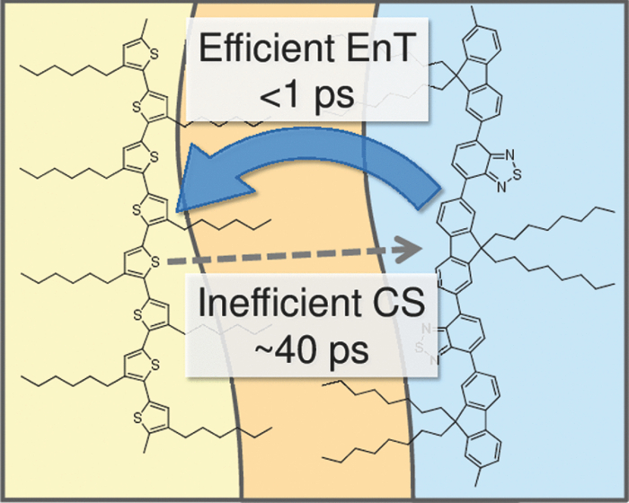 On the other hand, as shown in Fig. 9, the separation distance between P3HT and PCBM is likely to be much shorter than that between P3HT and F8BT, because PCBM is a small molecule and hence can be in direct contact with the P3HT main chain. Therefore, polarons can be promptly generated at the interface and also efficiently generated even after the exciton migration. Such intercalation of PCBM molecules has been proposed for several polymer/fullerene blends.22 Although there is insufficient room between the side chains of P3HT to allow the intercalation of PCBM in a crystalline phase, there would be sufficient room for the intercalation in a disordered phase such as at the interface. We therefore propose that the different interfacial structure is one of the reasons for the significant difference in the charge generation dynamics between P3HT/F8BT and P3HT/PCBM blends. Fig. 9Schematic illustration of the proposed interfacial structure at the interface of P3HT and PCBM. PCBM molecules closely contact with P3HT main chains. As a result, polarons can be promptly generated at the interface (upper arrow) and also efficiently generated even after the exciton migration (bottom arrows). 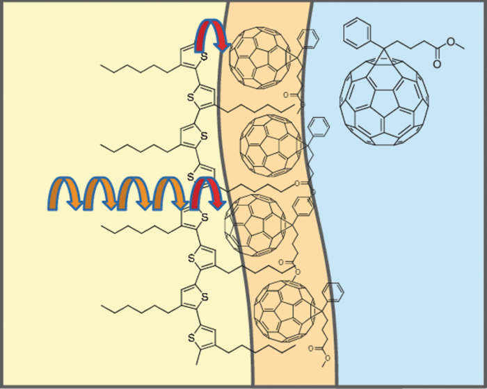 5.ConclusionIn P3HT/F8BT blend films, F8BT singlet excitons are efficiently transferred to P3HT domains by energy transfer in a picosecond. Upon the excitation at 400 nm, at least 60% of the P3HT singlet excitons should be located near the interface of P3HT and F8BT. If the following charge separation in P3HT/F8BT blends were as efficient as in P3HT/PCBM blends, 60% of polarons could be observed immediately after the laser excitation as we have reported previously. However, no polarons were observed at 0 ps in P3HT/F8BT blends. Furthermore, the charge separation from P3HT singlet excitons was as slow as 40 ps, which is much slower than the delayed polaron formation observed for P3HT/PCBM blends due to the exciton diffusion. The polaron generation efficiency was only ∼15%, which is much smaller than that of P3HT/PCBM blends (>80%). We therefore conclude that the charge generation is not efficient at the P3HT/F8BT interface compared to the P3HT/PCBM interface. At both interfaces, there are LUMO–LUMO offsets large enough for excitons to dissociate into free carriers. We speculate that the significant difference in the charge generation dynamics is mainly due to the difference in interfacial structure. In P3HT/F8BT blends, P3HT donor main chains are likely to be separated from F8BT acceptor main chains by ∼1 nm because of bulky long alkyl chains. This separation distance is short enough for the efficient energy transfer from F8BT to P3HT but too long for the following charge separation. In P3HT/PCBM blends, PCBM acceptor molecules are likely to contact with P3HT donor main chains because they are small molecules. These findings suggest that not only the electronic properties such as LUMO–LUMO offset and electron mobility but also the interfacial structures should be taken into account in the molecular design for highly efficient polymer/polymer solar cells. AcknowledgmentsThis work was supported by the JST PRESTO program (Photoenergy and Conversion Systems and Materials for the Next-Generation Solar Cells) and the Global COE program (International Center for Integrated Research and Advanced Education in Materials Science) from the Ministry of Education, Culture, Sports, Science, and Technology, Japan. ReferencesJ. J. M. Halls, C. A. Walsh, N. C. Greenham, E. A. Marseglia, R. H. Friend, S. C. Moratti, and A. B. Holmes,
“Efficient photodiodes from interpenetrating polymer networks,”
Nature (London), 376 498
–500
(1995). http://dx.doi.org/10.1038/376498a0 Google Scholar
G. Yu, J. Gao, J. C. Hummelen, F. Wudl, and A. J. Heeger,
“Polymer photovoltaic cells: Enhanced efficiencies via a network of internal donor–acceptor heterojunctions,”
Science, 270 1789
–1791
(1995). http://dx.doi.org/10.1126/science.270.5243.1789 Google Scholar
H.-Y. Chen, J. Hou, S. Zhang, Y. Liang, G. Yang, Y. Yang, L. Yu, Y. Wu, and G. Li,
“Polymer solar cells with enhanced open-circuit voltage and efficiency,”
Nat. Photonics, 3 649
–653
(2009). http://dx.doi.org/10.1038/nphoton.2009.192 Google Scholar
Y. Liang, Z. Xu, J. Xia, S.-T. Tsai, Y. Wu, G. Li, C. Ray, and L. Yu,
“For the bright future—bulk heterojunction polymer solar cells with power conversion efficiency of 7.4,”
Adv. Mater., 22 E135
–E138
(2010). http://dx.doi.org/10.1002/adma.200903528 Google Scholar
M. A. Green, K. Emery, Y. Hishikawa, and W. Warta,
“Solar cell efficiency tables (version 37),”
Prog. Photovolt.: Res. Appl., 19 1789
–1791
(2011). http://dx.doi.org/10.1002/pip.1088 Google Scholar
C. R. McNeill, A. Abrusci, J. Zaumseil, R. Wilson, M. J. McKieman, J. H. Burroughes, J. J. M. Halls, N. C. Greenham, and R. H. Friend,
“Dual electron donor/electron acceptor character of a conjugated polymer in efficient photovoltaic diodes,”
Appl. Phys. Lett., 90 193506
(2007). http://dx.doi.org/10.1063/1.2738197 Google Scholar
T. W. Holcombe, C. H. Woo, D. F. J. Kavulak, B. C. Thompson, and J. M. J. Fréchet,
“All-polymer photovoltaic devices of poly(3-(4-n-octyl)-phenylthiophene) from Grignard methathesis (GRIM) polymerization,”
J. Am. Chem. Soc., 131 14160
–14161
(2009). http://dx.doi.org/10.1021/ja9059359 Google Scholar
W. Ma, C. Yang, X. Gong, K. Lee, and A. J. Heeger,
“Thermally stable, efficient polymer solar cells with nanoscale control of the interpenetrating network morphology,”
Adv. Funct. Mater., 15 1617
–1622
(2005). http://dx.doi.org/10.1002/adfm.200500211 Google Scholar
G. Li, V. Shrotriya, J. Huang, Y. Yao, T. Moriarty, K. Emery, and Y. Yang,
“High-efficiency solution processable polymer photovoltaic cells by self-organization of polymer blends,”
Nat. Mater., 4 864
–868
(2005). http://dx.doi.org/10.1038/nmat1500 Google Scholar
Y. Kim, S. Cook, S. M. Tuladhar, S. A. Choulis, J. Nelson, J. R. Durrant, D. D. C. Bradley, M. Giles, I. McCulloch, C.-S. Ha, and M. Ree,
“A strong regioregularity effect in self-organizing conjugated polymer films and high-efficiency polythiophene:fullerene solar cells,”
Nat. Mater., 5 197
–203
(2006). http://dx.doi.org/10.1038/nmat1574 Google Scholar
J. Y. Kim, S. H. Kim, H.-H. Lee, K. Lee, W. Ma, X. Gong, and A. J. Heeger,
“New architecture for high-efficiency polymer photovoltaic cells using solution-based titanium oxide as an optical spacer,”
Adv. Mater., 18 572
–576
(2006). http://dx.doi.org/10.1002/adma.200501825 Google Scholar
M. D. Irwin, B. D. Buchholz, A. W. Hains, R. P. H. Chang, and T. J. Marks,
“p-Type semiconducting nickel oxide as an efficiency-enhancing anode interfacial layer in polymer bulk-heterojunction solar cells,”
Proc. Natl. Acad. Sci. U.S.A., 105 2783
–2787
(2008). http://dx.doi.org/10.1073/pnas.0711990105 Google Scholar
Y. Kim, S. Cook, S. A. Choulis, J. Nelson, J. R. Durrant, and D. D. C. Bradley,
“Organic photovoltaic devices based on blends of regioregular poly(3-hexylthiophene) and poly(9,9-dioctylfluorene-co-benzothiazole),”
Chem. Mater., 16 4812
–4818
(2004). http://dx.doi.org/10.1021/cm049585c Google Scholar
C. R. McNeill, A. Abrusci, I. Hwang, M. A. Ruderer, P. M.-Buschbaum, and N. C. Greenham,
“Photophysics and photocurrent generation in polythiophene/polyfluorene copolymer blends,”
Adv. Funct. Mater., 19 3103
–3111
(2009). http://dx.doi.org/10.1002/adfm.200900801 Google Scholar
V. D. Mihailetchi, J. K. J. van Duren, P. W. M. Blom, J. C. Hummelen, R. A. J. Janssen, J. M. Kroon, M. T. Rispens, W. J. H. Verhees, and M. M. Wienk,
“Electron transport in a methanofullerene,”
Adv. Funct. Mater., 13 43
–46
(2003). http://dx.doi.org/10.1002/adfm.200390004 Google Scholar
M. C. Scharber, D. Mühlbacher, M. Koppe, P. Denk, C. Waldauf, A. J. Heeger, and C. J. Brabec,
“Design rules for donors in bulk-heterojunction solar cells—towards 10% energy-conversion efficiency,”
Adv. Mater., 18 789
–794
(2006). http://dx.doi.org/10.1002/adma.200501717 Google Scholar
J. Guo, H. Ohkita, H. Benten, and S. Ito,
“Charge generation and recombination dynamics in poly(3-hexylthiophene)/fullerene blend films with different regioregularities and morphologies,”
J. Am. Chem. Soc., 132 6154
–6164
(2010). http://dx.doi.org/10.1021/ja100302p Google Scholar
S. Yamamoto, J. Guo, H. Ohkita, and S. Ito,
“Formation of methanofullerene cation in bulk heterojunction polymer solar cells studied by transient absorption spectroscopy,”
Adv. Funct. Mater., 18 2555
–2562
(2008). http://dx.doi.org/10.1002/adfm.200800411 Google Scholar
J. Guo, H. Ohkita, H. Benten, and S. Ito,
“Near-IR femtosecond transient absorption spectroscopy of ultrafast polaron and triplet exciton formation in polythiophene films with different regioregularities,”
J. Am. Chem. Soc., 131 16869
–16880
(2009). http://dx.doi.org/10.1021/ja906621a Google Scholar
J. Jaczewska, I. Raptis, A. Budkowski, D. Goustouridis, J. Raczkowska, M. Sanopoulou, E. Pamuła, A. Bernasik, and J. Rysz,
“Swelling of poly(3-alkylthiophene) films exposed to solvent vapors and humidity: Evaluation of solubility parameters,”
Synth. Met., 157 726
–732
(2007). http://dx.doi.org/10.1016/j.synthmet.2007.07.015 Google Scholar
S. Nilsson, A. Bernasik, A. Budkowski, and E. Moons,
“Morphology and phase segregation of spin-casted films of polyfluorene/PCBM blends,”
Macromolecules, 40 8291
–8301
(2007). http://dx.doi.org/10.1021/ma070712a Google Scholar
A. C. Mayer, M. F. Toney, S. R. Scully, J. Rivnay, C. J. Brabec, M. Scharber, M. Koppe, M. Heeney, I. McCulloch, and M. D. McGehee,
“Bimolecular crystals of fullerenes in conjugated polymers and the implications of molecular mixing for solar cells,”
Adv. Funct. Mater., 19 1173
–1179
(2009). http://dx.doi.org/10.1002/adfm.200801684 Google Scholar
BiographyHideo Ohkita is an associate professor at the Department of Polymer Chemistry in Kyoto University and concurrently a researcher of PRESTO, Japan Science and Technology Agency (JST). He obtained a doctoral degree from Kyoto University in 1997. He became an assistant professor in 1997 and was promoted to an associate professor in 2006. He worked with Professor Durrant as an academic visitor at Imperial College London (London, United Kingdom) from 2005 to 2006. His research interests include studying the fundamental processes of photophysics and photochemistry in polymer systems such as excitation energy and electron transfer. His current research focuses on spectroscopic approach to polymer solar cells. Junya Kosaka has been a graduate student in Professor Shinzaburo Ito's group at the Department of Polymer Chemistry in Kyoto University since 2009. He graduated from Kyoto University in 2009. His research focuses on photophysics in polymer/polymer blend solar cells. Jiamo Guo has been a graduate student in Professor Shinzaburo Ito's group at the Department of Polymer Chemistry in Kyoto University from 2005 to 2010. He graduated from Beijing Institute of Graphic Communication (Beijing, China) in 2003 and obtained a doctoral degree from Kyoto University in 2010. His research focuses on photophysics in polymer-based solar cells. Hiroaki Benten is an assistant professor at the Department of Polymer Chemistry in Kyoto University. He graduated in 2000 and obtained his doctoral degree of Engineering from Kyoto University in 2005. He was a postdoctoral fellow in Kyoto University from 2005 to 2006. He worked as a postdoctoral fellowship for research abroad in Max-Planck Institute for Polymer Research (Mainz, Germany) in the laboratory of Professor Knoll from 2006 to 2008. He was appointed his present position in 2008. His research interests are photophysics and photochemistry in polymers and their interfaces. Shinzaburo Ito is a professor at the Department of Polymer Chemistry in Kyoto University. He graduated in 1973 and obtained his doctoral degree of Engineering from Kyoto University in 1981. He was appointed as a research instructor of Kyoto University in 1979. He was a guest scientist of Max-Planck Institute for Polymer Research (Mainz, Germany) in the laboratory of Professor Knoll from 1991 to 1992, and was also a visiting research fellow of RIKEN (Wako, Japan) during 1993 to 1999 and was promoted to his present position in 1999. His research interests encompass polymer nano-structure, polymer photophysics and photochemistry, ultra-thin films and their optical and electrical properties. He has been an Asian Editor of Polymer in physical chemistry and functionality field since July 1999. |