|
|
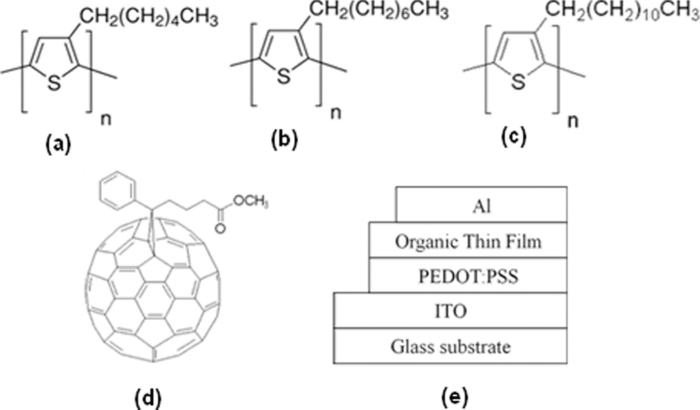
1.IntroductionResearchers are investigating the production of low cost, flexible, low weight organic thin film solar cells.1 Organic Solar cells (OSCs) based on bulk-heterojunction fabricated by a poly(3-hexylthiophene)(P3HT)/[6,6]-phenyl C71 butyric acid methyl ester (PC71BM) composite film have enabled a power conversion efficiency of 5%.2 However, the performance of OSC is markedly lower than that of inorganic solar cells.3 Therefore, with practical organic solar cells in mind, it is important to address these problems. The power conversion efficiency (PCE) of OSC was improved with thermal annealing treatment and by adding poor solvent.4, 5, 6 In our recent investigation, the OSC fabricated by the active layer of P3HT poly(3-octylthiophene) (P3OT) PC71BM thin film was improved compared to that without P3OT. In this study, the OSC of the active layers of a P3HT/PC71BM thin film prepared by P3OT and poly(3-dodecylthiophene) (P3DDT) additives are fabricated and the PCEs are measured and investigated. 2.Experimental2.1.MaterialsThe p-type semiconductors of P3HT, P3OT and P3DDT and the n-type semiconductor of PC71DM were adopted for fabrication of the active layer of organic thin film solar cells. In the chlorobenzene solution of 1 cc, P3HT/PC71BM is the ratio of 12 mg/12 mg, P3HT/P3OT/PC71BM is the ratio of 9 mg/3 mg/12 mg, and P3HT/P3DDT/PC71BM is the ratio of 9 mg/3 mg/12 mg. This ratio indicated the best performances compared to other ratios. Fig. 1 shows a schematic cross section of an organic thin film solar cell and the chemical structures of P3HT, P3OT, P3DDT, and PC71BM. 2.2.Device FabricationOSCs were fabricated as follows. The active layer was prepared by the spin-coating method. The indium tin oxide (ITO) coated glass substrate was cleaned with detergent, deionized water, acetone, and ethanol according to an ultrasonication method for 15 min each, and then was treated with UV-ozone for 30 min. After cleaning the substrate, a poly(3,4-ethylenedioxythiophene)/poly(styrenesulfonate) (PEDOT-PSS) layer was prepared on the ITO (spinning speed: 4000 rpm and spinning time: 30 s). Then, the substrate was placed in an oven at 110°C for 10 min to remove moisture. Subsequently, the P3HT/PC71BM, P3HT/P3OT/PC71BM or P3HT/P3DDT/PC71BM thin films were prepared on the surface of the PEDOT-PSS layer, respectively (spinning speed: 1000 rpm and spinning time: 30 s). Afterward, the Al electrode was evaporated on the thin film by thermal evaporation in vacuum (2×10⁻⁶ Torr). Finally, thermal annealing was carried out by directly placing the device on a hotplate in a glove-box filled with N2 at 110°C for 1 min. For comparison, we fabricated the OSCs having an active layer of P3HT/ PC71BM thin film. 3.Results and DiscussionFigure 2 shows the characteristics (J-V ) of the current density versus the voltage of the organic thin film solar cells fabricated from various active layers, respectively. Table 1 summarizes the open circuit voltage (Voc), short circuit current density (Jsc), fill factor (FF), and PCE. From these results, the Voc of the OSC consisting of (a) P3HT/PC71BM thin film is 0.56 V. The FF is 0.55. The PCE is 1.01%. The Voc of the OSC consisting of (b) P3HT/PC71BM thin film is 0.54 V. The FF is 0.46. The PCE is 1.72%. The Voc of the OSC consisting of (c) P3HT/P3OT/PC71BM thin film increases from 0.54 to 0.66 V. The FF also increases from the value of 0.46 to the value of 0.49. However, the Jsc decreases from the value of 6.92 to the value of 4.48 mA/cm2. Therefore, the PCE is 1.45%. On the other hand, the Voc of the OSC consisting of (d) P3HT/P3DDT/PC71BM thin film increases to 0.57 V, but the FF decreases to 0.42 and the Jsc is 3.42 mA/cm2 so that the PCE decreases to 0.83%. Table 1Shows each parameter of the organic solar cells from the J-V characteristics.
Fig. 2Shows the J-V characteristics of the organic solar cells fabricated by the thin films of (a) P3HT/PC71BM, (b) P3HT/PC71BM (thermal annealing 110°C), (c) P3HT/P3OT/PC71BM (thermal annealing 110°C), and (d) P3HT/P3DT/PC71BM (thermal annealing 110°C). 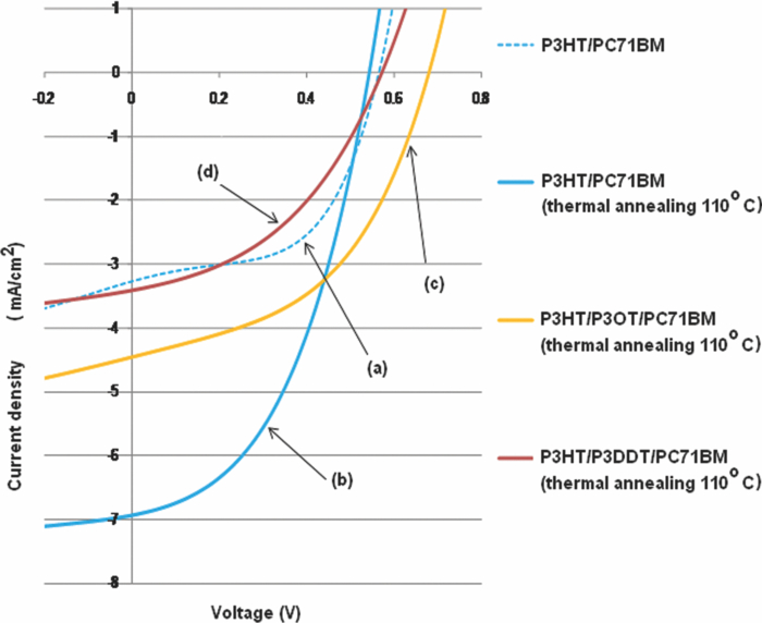 When performing the properties of P3HT/PC71BM, P3HT/P3OT/PC71BM, and P3HT/P3DDT/PC71BM thin films, the XRD profiles of P3HT/PC71BM, P3HT/P3OT/PC71BM and P3HT/P3DDT/PC71BM thin films were measured and characterized. For the same reason, the UV-vis spectra were measured and characterized. Figure 3 shows the UV-vis spectra of the thin films of (a) P3HT/PC71BM, (c) P3HT/P3OT/PC71BM, and (e) P3HT/P3DDT/PC71BM. Their thin films were prepared by spin coating. Then, the thermal annealing of each of the thin films was performed at a temperature of 110°C for 1 min. The main absorption peak of the UV-vis spectra of both thin films of P3HT/P3OT/PC71BM and P3HT/P3DDT/PC71BM treated by thermal annealing were shifted to the longer wavelength-side than that compared with both untreated samples from 480 to 520 nm and the absorption shoulder clearly appeared at 560 and 610 nm. This indicates that their thin films form a P3HT grain and PC71BM aggregation.7 The main absorption peak of the P3HT/PC71BM thin film treated by thermal annealing was shifted much longer on the wavelength-side than that compared with both thin films of P3HT/P3OT/PC71BM and P3HT/P3DDT/PC71BM treated by thermal annealing. The difference between rms roughness of P3HT/PCBM thin film (where PCBM is [6,6]-phenyl-C71-butyric acid methyl ester) and P3OT/P3HT/PCBM thin film can be observed from the surface morphology of the AFM image. The rms roughness of a P3HT/P3OT/PCBM thin film is 1.53 nm. The RMS roughness of a P3HT/PCBM thin film is 0.58 nm. This indicates that the thin films form larger P3OT grains because of the molecular self-assembly of P3OT. Moreover, the molecular self-assembly of P3DDT is larger than that of P3HT.8 In these cases, the thin films are alone. Fig. 3UV/ V is spectra of organic thin films fabricated by (a) P3HT/PC71BM, (b) P3HT/ PC71BM (thermal annealing 110°C), (c) P3HT/P3OT/PC71BM, (d) P3HT/P3OT/PC71BM (thermal annealing 110°C), (e) P3HT/P3DDT/PC71BM, and (f) P3HT/P3DDT/PC71BM (thermal annealing 110°C). 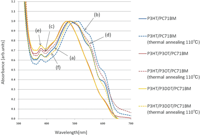 Figure 4 shows the XRD profiles of the P3HT/PC71BM and P3HT/P3OT/PC71BM thin films before and after the thermal treatment operated at 110°C for 1 min. Both show the same diffraction peak, and the diffraction peak has the maximum diffraction peak at 5.2°. The lattice space distance of d is 1.6 nm. The diffraction intensity obtained from XRD profiles is also the same. The hwhm of “half width at half maximum” is larger than that compared to a P3HT/PC71BM thin film. Furthermore, the peak intensity of the P3HT/P3OT/PC71BM thin film treated by thermal annealing is lower than that compared with the untreated P3HT/PC71BM thin film. This indicates that it is difficult to form the P3HT grain and PC71BM aggregation in the P3HT/P3OT/PC71BM thin film treated by thermal annealing. This also suggests that the side-chain of P3OT is critically related to the formation of the grain. Therefore, the active layer becomes almost amorphous. The carrier mobility of the active layer decreases. Both the current density of the OSC's prepared by the active layers added by additive P3OT and additive P3DDT decrease. On the other hand, the diffraction peaks are not observed from the XRD profile of the P3HT/P3DDT/PC71BM thin film (not displayed in Fig. 4) because the alkyl side-chain of P3DDT is longer than the one of P3OT. Since the P3HT active layer has much higher crystallization than those of P3OT and P3DDT active layer, the alkyl side-chains between P3HT molecules interdigitate toward the perpendicular direction to the substrate.7 With mixed P3HT and P3OT or P3DDT molecules, the interdigitation between P3HT molecules is disturbed and the crystallization of the P3HT thin film is low. Fig. 4XRD profiles. (a) P3HT/PC71BM thin film treated with thermal annealing and without thermal annealing. (b) P3HT/P3OT/PC71BM thin film treated with thermal annealing and without thermal annealing. 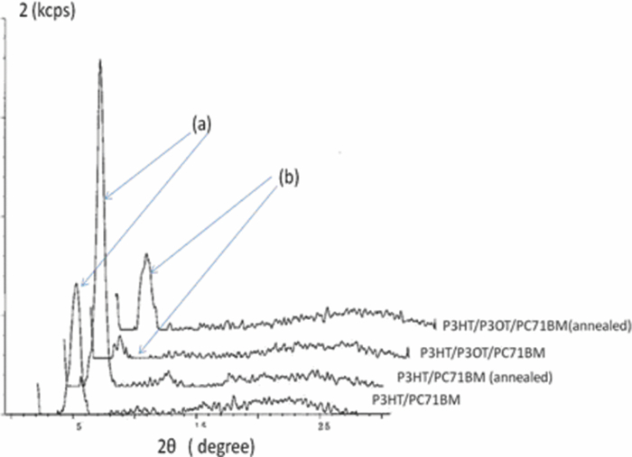 Now, the solvent annealing of both surfaces of the P3HT/P3OT/PC71BM and P3HT/P3DDT/PC71BM before vacuum deposited Al electrode was performed by N-methyl-2-pyrrolidone for the annealing time of 10 min. After that, these active layers were treated by thermal annealing at 110°C for 1 min. Then, the surface treatment of ethanol was performed to enhance the smoothness of the surface of the active layer after solvent annealing (spin speed: 2000 rpm and spinning time: 60 s). Figure 5 shows the UV-vis spectra of P3HT/P3OT/PC71BM thin film treated by thermal annealing and/or solvent annealing. The absorption peak of the P3HT/P3OT/PC71BM thin film treated with both solvent and thermal annealing shifts from 480 to 510 nm. This absorption peak shifts to the longer wavelength side than that treated by only thermal annealing. This indicates that the P3HT grain and PC71BM aggregation form in the thin film by solvent annealing. Figure 6 shows the UV-vis spectra of P3HT/P3DDT/PC71BM thin film treated by thermal annealing and/or solvent annealing. The absorption peak of P3HT/P3DDT/PC71BM thin film hardly changes by solvent annealing. This indicates that the solvent annealing does not affect the formation of the P3HT grain and PC71BM aggregation because the alkyl side-chain length of the P3DDT molecule is longer than that of the P3OT molecule. Fig. 5UV/V is spectra. (a) P3HT/PC71BM thin film was treated by thermal annealing. (b) Bare P3HT/P3OT/PC71BM thin film. (c) P3HT/P3OT/PC71BM thin film treated with thermal annealing. (d) P3HT/P3OT/PC71BM thin film treated with both thermal annealing and solvent annealing. 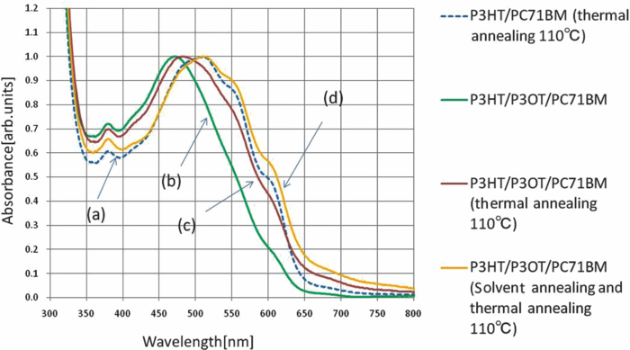 Fig. 6UV/V is spectra. (a) P3HT/PC71BM thin film was treated by thermal annealing. (b) Bare P3HT/P3DDT/PC71BM thin films. (c) P3HT/P3DDT/PC71BM thin films was treated with thermal annealing. (d) P3HT/P3DDT/PC71BM thin films treated by solvent annealing and after that, thermal annealing. 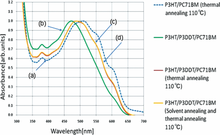 Figure 7 shows the J-V characteristics of the organic solar cells fabricated with the active layer of a. the P3HT/PC71BM treated by thermal annealing b. the P3HT/P3OT/PC71BM treated by thermal annealing, and d. the P3HT/P3OT/PC71BM treated by both solvent annealing and thermal annealing. Table 2 summarizes each of the parameters of the devices: Voc, Jsc, FF and PCE. The Voc of the prepared OSC by the active layer of the P3HT/P3OT/PC71BM thin film treated with both the thermal and solvent annealing decreases from 0.66 to 0.62 V. In contrast, Jsc increases from 4.48 to 6.55 mA/cm2 and the FF improves to 0.51. Based on these findings, the PCE is improved from 1.45% to 2.07%. Table 2Each parameter estimated from the J-V characteristics of the organic solar cells.
Fig. 7Shows the J-V characteristics of the organic solar cells fabricated with the active layer of (a) the P3HT/PC71BM treated by thermal annealing, (b) the P3HT/P3OT/PC71BM treated by thermal annealing, and (d) the P3HT/P3OT/PC71BM treated by both solvent annealing and thermal annealing. 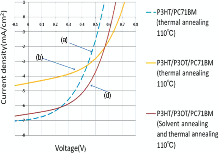 Typically, the open circuit voltage of Voc depends on the difference between the HOMO of the donor and the LOMO of the acceptor.8 Therefore, the decrease of the Voc with solvent-annealing can be explained by the shunt resistance of the OSC. The solvent annealing improves the interpenetrating network of the active layer of OSC. In other words, the difference between the band gap before and after solvent annealing affects the Voc because the generated carriers of the active layer are related to the decrease of Voc. The redshifted absorption of the UV-vis spectrum results from the decrease of the energy band gap. Therefore, the lowering of the Voc of the solvent-annealed device can be explained by the reduced optical band gap of the donor molecules.6 Figure 8 shows the J-V characteristics of organic solar cells fabricated by the active layers of (a) P3HT/PC71BM treated with thermal annealing, (c) P3HT/P3DDT/PC71BM treated with thermal annealing and (e) P3HT/P3DDT/PC71BM treated with both solvent and thermal annealing, respectively. In the OSC fabricated by the active layer consisting of the P3HT/P3DDT/PC71BM thin film treated by both solvent and thermal annealing, the values of Voc and Jsc decrease to 0.45 V and to 1.63 mA/cm2 respectively. The FF decreases to 0.31. The PCE decreases to 0.22%. This indicates that the alkyl side-chain length of the P3DDT molecule is longer than that of the P3OT molecule. Fig. 8J-V characteristics of organic solar cells. (a) P3HT/PC71BM treated with thermal annealing. (c) P3HT/P3DDT/PC71BM treated with thermal annealing. (e) P3HT/P3DDT/PC71BM treated with both solvent and thermal annealing. 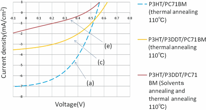 Figures 9, 10, 11, 12 show the AFM images of the surfaces of P3HT/PC71BM, P3HT/P3OT/PC71BM, and P3HT/P3OT/PC71BM treated with thermal annealing and P3HT/P3OT/PC71BM thin film treated by both solvent and thermal annealing. From the rms roughness of the AFM images shown in Figs. 9, 10, the surface of the active layer of the P3HT/P3OT/PC71BM thin film is smoother than that of the P3HT/PC71BM thin film (Table 3). Therefore, the active layer of P3OT additive is lower in crystallinity than P3OT non-additive. This indicates that the interface between the P3HT grain and PC71BM aggregation decreases by P3OT additive. In other words, the series resistance of OSC is enhanced by P3OT additive so that the PCE of OSC is lower than that of P3OT non-additive. From the rms roughness of the AFM images of Figs. 11, 12, the surface of the P3HT/ P3OT/PC71BM thin film treated by both solvent and thermal annealing treatments is smoother than that with P3HT/P3OT/PC71BM thin film treated by thermal annealing. This indicates that the homogeneity of the P3HT/ P3OT/PC71BM thin film treated by both solvent and thermal annealing treatments is improved by both annealing treatments. This also suggests that the interpenetrating network of the P3HT/ P3OT/PC71BM thin film treated by both annealing treatments is much better than that of the P3HT/P3OT/PC71BM thin film treated by thermal annealing.4, 9 This indicates that the morphology of the P3HT/P3OT/PC71BM thin film is optimized by P3OT additive. In other words, the fabricated OSC by the P3HT/ P3OT/PC71BM thin film treated by both solvent and thermal annealing treatments gives the best performance. Table 3AFM image of the surfaces of each active layers.
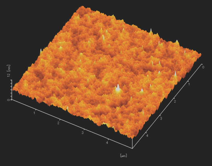
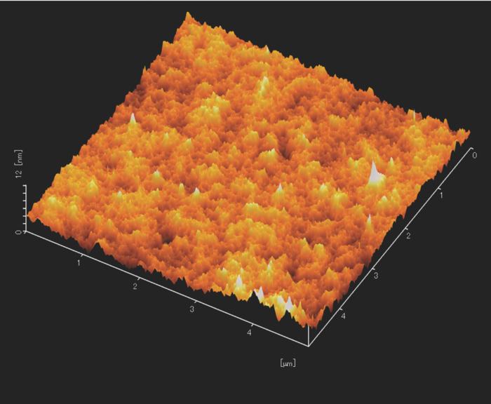
Fig. 9AFM image of the surface of the thin film fabricated from the chlorobenzene solution of P3HT/PC71BM (12 mg/12 mg) by a spin-coating method. 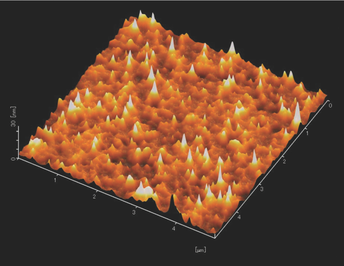 Fig. 10AFM image of the surface of the thin film treated by thermal annealing and fabricated from the chlorobenzene solution of P3HT/PC71BM (12 mg/12 mg) by a spin-coating method. 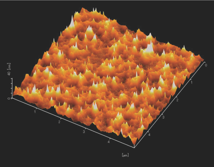 4.ConclusionThe performance of organic thin film solar cells is improved by the active layer of P3OT additive and both solvent annealing and thermal annealing treatments. The surface of P3HT/P3OT/PC71BM thin film treated by both solvent annealing and thermal annealing treatments is smoother than that of P3H/PC71BM thin film. Therefore, the performance of the organic thin film solar cell fabricated by the P3HT/P3OT/PC71BM thin film treated by both solvent annealing and thermal annealing treatments is increased. The PCE reaches 2.07% as a result of the improvement. AcknowledgmentsThis work was partially supported by MEXT Private University Project Grant under Contract No. S1001033 and also supported by the Research Foundation for the Electrotechnology of Chubu. ReferencesG. Yu, J. Gao, J. C. Hummelen, F. Wudl, and A. J. Heeger,
“Polymer photovoltaic cells: Enhanced efficiencies via a network of internal donor-acceptor heterojunctions,”
Science, 270 1789
–1791
(1995). http://dx.doi.org/0.1126/science.270.5243.1789 Google Scholar
G. Li, V. Shrotriya, J. Huang, Y. Yao, T. Moriarty, K. Emery, and Y. Yang,
“High-efficiency solution processable polymer photovoltaic cells by self-organization of polymer thins,”
Nat. Mater., 4 864
–868
(2005). http://dx.doi.org/10.1038/nmat1500 Google Scholar
O. Schultz, S. W. Glunz, and G. P. Willeke,
“Accelerated publication multicrystalline silicon solar cells exceeding 20% efficiency,”
Prog. Photovoltaics, 12 553
–558
(2004). http://dx.doi.org/10.1002/pip.583 Google Scholar
S. K. Park, Y.-H. Kim, and J.-I. Han,
“Effect of annealing treatment and surface morphology on power conversion in organic photovoltaics,”
Jpn. J. Appl. Phys., 48 081505
(2009). http://dx.doi.org/10.1143/JJAP.48.081505 Google Scholar
D. Placencia, W. Wang, R. C. Shallcross, K. W. Nebesny, M. Brumbach, and N. R. Armstrong,
“Organic photovoltaic cells based on solvent-annealed, textured titanyl phthalocyanine/C60 heterojunctions,”
Adv. Funct. Mater., 19 1913
–1921
(2009). http://dx.doi.org/10.1002/adfm.200801723 Google Scholar
J. H. Park, J. S. Kim, J. H. Lee, W. H. Lee, and K. Cho,
“Effect of annealing solvent solubility on the performance of poly(3-hexylthiophene)/methanofullerene solar cells,”
J. Phys. Chem. C, 113 17579
(2009). http://dx.doi.org/10.1021/jp9029562 Google Scholar
K. Sethuraman, S. Ochiai, Y. Yamada, S. Mototani, K. Kojima, A. Ohashi, and T. Mizutani,
“Third-harmonic generation of regioregular poly(3-hexylthiophene) thin films prepared using two solution methods,”
Jpn. J. Appl. Phys., 47 450
–454
(2008). http://dx.doi.org/10.1143/JJAP.47.450 Google Scholar
J. Ru, T. Mizutani, K. Kojima, and S. Ochiai,
“Third-order nonlinear optical characteristics and the morphologies of polythiophene derivative thin films fabricated by the solution method,”
Proc. SPIE, 7413 741303
(2009). http://dx.doi.org/10.1117/12.826837 Google Scholar
Y. Liang, Z. Xu, J. Xia, S.-T. Tsai, Y. Wu, G. Li, C. Ray, and L. Yu,
“For the bright future-bulk heterojunction polymer solar cells with power conversion efficiency of 7.4%,”
Adv. Mater., 22 E135
–E138
(2010). http://dx.doi.org/10.1002/adma.200903528 Google Scholar
|