|
|
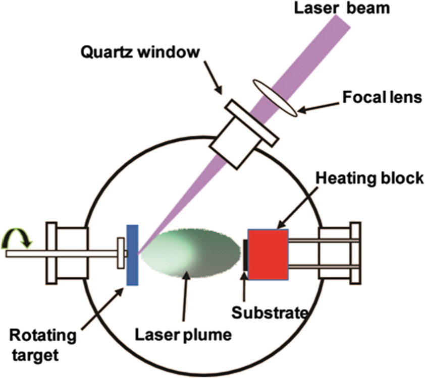
1.IntroductionRecent advances in semiconductor processing techniques have enabled microelectronic and microelectromechanical devices to significantly decrease in size. However, the dimensions of the power sources required to operate these microdevices have not undergone commensurate size reductions due to their volumetric three-dimensional (3-D) characteristics, limiting the ability of these devices to function autonomously. In order to capitalize on the advantages of miniaturization in autonomous microelectronics, such as wireless network microsensors, the size of their power sources needs to be correspondingly reduced. Many techniques have been utilized to fabricate micropower sources, such as thin-film, stretchable, and 3-D batteries. 1 – 4 Among these techniques, laser-based processes such as pulsed laser deposition (PLD) and laser-induced forward transfer (LIFT), have been recognized as practical approaches to integrate various types of micropower sources such as thin-film microbatteries, capacitors, and solar cells, with various microdevices. For the purposes of this review, micropower sources are defined as those where the total mass of active material does not exceed 10 g and can be in the form of thin films ( total thickness) or thick films (of the order of tens of microns) across a wide range of areas ( to ) depending on the application. A combination of different types of power sources is necessary to meet the power demand for certain types of microdevices. 5 For example, wireless sensors possess several different power requirements. In stand-by mode, they only consume a few mW of power, while in data collection mode, they consume less than 100 mW with several hundreds of mW required to transmit the data to a remote system. In this example, a constant low power ( mW) can be delivered by a lithium microbattery, a short burst of high power can be supplied by an ultracapacitor, and during long intervals in stand-by mode, power sources can be recharged by harvesting energy from the environment using a solar cell. As this review will show, laser processing techniques are ideally suited to prototype, optimize, and fabricate these electrochemical energy storage components for hybrid micropower systems. Furthermore, laser-based processes can be used for modifying the layers of active materials without damaging the substrate underneath, which is ideally suited for developing power sources on flexible plastic substrates. 6 Laser processing techniques can also directly integrate the electrochemical component into the device package, reducing the size and weight of the entire system. Altogether, laser-based processing techniques are a promising approach for developing micropower sources for microelectronic devices. In the following sections, we provide a brief review of the use of PLD techniques for thin-film microbatteries, the use of LIFT techniques for thick-film microbatteries and solar cells, and the use of laser surface processing for modifying active materials. 2.Pulsed Laser Deposition Technique for Thin-Film MicrobatteriesA schematic illustration of the basic components for a PLD setup is shown in Fig. 1. Typically, an ultraviolet (UV) excimer laser, such as ArF (193 nm), KrF (248 nm), and XeCl (308 nm), is employed with a pulse width of tens of nanoseconds or shorter. Other types of lasers, such as the various harmonics of a Nd:YAG laser, have also been employed for PLD. The principle of the PLD process is very simple. It uses a pulsed laser beam to evaporate material from a target forming a thin film on a substrate retaining the target composition. The high-power laser beam is focused inside a vacuum chamber onto the target typically at an angle of incidence of 45 deg with respect to its surface perpendicular direction. The ablation of the target produces a visible plasma plume that expands from the target to the substrate. The target is typically rotated in order to avoid its fast deterioration and keep its surface under approximately constant conditions. The substrate is located facing the target at a distance in the range 4 to 10 cm. This process can be performed at a dynamic range of pressures from ultra high vacuum (UHV) to high pressures (typically up to 1 Torr) and any kind of inert or reactive atmosphere can be used. Another advantage of the PLD technique is its capability to grow multilayer thin films using a multitarget carousel system. The laser beam can easily be alternatively focused over two or more targets, leading to a sequential ablation process. This configuration is ideally suited for manufacturing complex stacks such as typical layered battery structures. An important feature of PLD is that the stoichiometry of the target can be retained in the deposited films. This is a result of the extremely high heating rates experienced by the target surface due to its strong interaction with the laser irradiation. When the laser fluence is low, the laser pulse simply heats the target and evaporates the target species. In this case, the evaporative flux from a multicomponent target can be determined by the vapor pressures of its constituents. As the laser fluence is increased, the ablation threshold is reached where the absorbed laser energy is higher than that needed for evaporation. In this case, the flux of vaporized species is not dependent on the vapor pressures of the constituent cations. This nonequilibrium process leads to the congruent evaporation of the target. This stoichiometry transfer between target and substrate is difficult to achieve with other physical vapor deposition techniques. Sputtering from a multicomponents’ target results in varying thin-film composition due to the difference in the partial vapor pressures (or sputtering yields) of the target components. 2.1.Thin-Film CathodeMost examples in the literature of PLD applied to the fabrication of microbatteries have focused on Li-metal and Li-ion electrochemistries. For a Li-ion microbattery, an ideal thin-film cathode should be a layered structure of lithiated oxides, such as and , and, therefore, it must be well crystallized. In order to improve the crystallinity of the thin films, postdeposition annealing is often required at a relatively high temperature. However, this high temperature annealing tends to damage the current collecting layers and substrate materials underneath the lithiated oxides. Furthermore, this high temperature annealing may create microcracks in the cathode films, leading to nonuniformity of the solid electrolyte in the sequential deposition step and, accordingly, shorting problems in the batteries. One of the important features in PLD is that the ejected species in the laser-induced plasma plume have a relatively high kinetic energy (10 to 100 eV), which is typically one order of magnitude higher than other physical vapor deposition techniques such as sputtering (5 to 10 eV) or evaporation ( ) 7 – 9 (see Table 1). Thus, PLD films crystallize at lower substrate temperatures compared to other physical vapor deposition techniques. 7 , 10 – 12 Table 1Kinetic energy of species and heat-treatment for LiCoO2 thin films grown by PLD and sputtering techniques.
As shown in Table 1, cathode thin films grown by PLD can be crystallized at temperatures as low as 300°C without postdeposition annealing. 13 In order to obtain better crystallization, postdeposition annealing (700°C–800°C) is required for cathode films grown by sputtering. 16 Since PLD films are well crystallized at relatively low temperatures (300°C–600°C) without any postdeposition annealing, PLD grown cathode thin films with high density and smooth surfaces without cracks, which are essential for high performance in thin-film batteries, are easily produced. 14 , 17 – 21 For a Li-ion microbattery, an ideal thin-film cathode should be a layered structure of lithiated oxides, such as and . The crystallographic orientations of the cathode thin films also affect the electrochemical activity. In PLD, the high supersaturation of the ablated flux leads to two-dimensional (2-D) island nucleation on the film surface, which is favorable for the layer-by-layer growth mode of the films. 8 Thus, it is easy to form highly oriented thin films by PLD. Xia et al reported that thin films grown by PLD show a preferred c-axis (003) orientation up to 500 nm thick. 15 Orientation of the cathode thin films can be controlled by using substrates with different orientations. PLD was successfully employed to grow the (003) oriented and (104) oriented thin films on and Au/MgO/Si substrates, respectively. 22 In PLD of cathode thin films, the substrate plays an important role in determining the microstructure of the films. cathode thin films were grown on stainless steel (SS) and Au substrates by PLD. 20 The films grown on the SS substrate formed a spinel structure due to the severe interdiffusion between the substrate and the film during the high temperature deposition process, while the film on the Au substrate exhibited a layered structure. The overall reversible capacity of the cell on the Au substrate showed (between 2.5 and 4.3 V), which is much higher than that of the SS substrate ( between 2.5 and 4.5 V). Thus, the cathode thin films grown on Au substrates by PLD were considered as a promising cathode material for thin-film microbatteries (see Table 2). The theoretical capacity of the cathode is . Table 2Electrochemical properties of thin-film cathodes and anodes prepared by PLD. SS represents stainless steel.
Although the stoichiometry of the films grown by PLD is normally close to that of the targets, it is very difficult for PLD to control the composition of volatile light elements such as lithium. 18 These light elements are easily scattered by background gas molecules or other species in the plasma, or are sputtered from the growing film by energetic species arriving at the substrate surface. Thus, in the case of lithium containing materials, the lithium content in the deposited thin films tends to be lower than that in the targets. This Li-deficiency in the film may cause structural changes and impurity formation, which will eventually deteriorate the electrochemical performance of the battery. One way to overcome this problem is through the use of targets containing excess . 13 , 18 , 22 , It was reported that cathode thin films with a desired lithium content can be obtained by PLD using a composite target of and 7.5 mol% , respectively. 18 The electrochemical analysis of the batteries based on these cathode thin films indicated that the charge and discharge capacities were observed to be 31–55 and , respectively. Well-textured cathode thin films were also successfully prepared by a nonstoichiometric target with 15% excess and their batteries showed reasonably good electrochemical performance ( ). 22 As discussed above, all of these features (crystallinity, layered structure, smooth surface, composition, and preferred orientation of the cathode films) are very important requirements to achieve better electrochemical properties of the cathode thin films. Table 2 shows the growth conditions and key electrochemical properties of thin-film cathodes prepared by PLD recently reported in the literature. 2.2.Thin-Film AnodeCarbon is the most commonly used anode material in commercial lithium-ion batteries. However, the use of carbon-based materials cannot meet the capacity demand due to their low theoretical capacities (i.e., , ). Among the various potential anode materials, silicon has been recognized as an alternative anode material since it has a maximum theoretical capacity which is 10 times higher than that of carbon ( , ). 28 However, its application has been impeded by the significant volume expansion in silicon during lithium insertion and extraction that results in loss of electrical contact to the current collector, leading to capacity fading. For amorphous silicon (a-Si) anodes, the volume expansion upon lithium insertion is homogeneously distributed and the effect of crack formation becomes less catastrophic compared to crystalline silicon (c-Si) due to the presence of defects and the absence of long range order. 22 , 29 The PLD technique was successfully utilized to deposit a-Si anode thin films on stainless steel substrates at room temperature 22 The a-Si anode thin film (120 nm thick) showed stable cycling behavior between 0.01 and 1.5 V for 50 cycles with a small fade rate in capacity of 0.2% per cycle. The a- cell provided a stable discharge capacity of between 1 and 4 V. 22 Some of the electrochemical properties of the a-Si anode thin films are also shown in Table 3. The film thickness plays an important role in the cycle life of the a-Si anode thin film. Increasing the film thickness causes severe capacity fading due to increased Li-ion diffusion length. Table 3Electrochemical properties of electrolyte thin-films prepared by PLD.
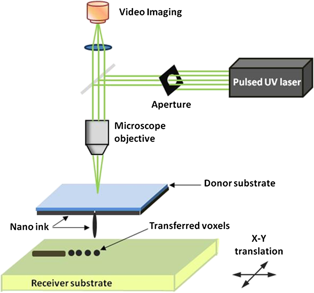
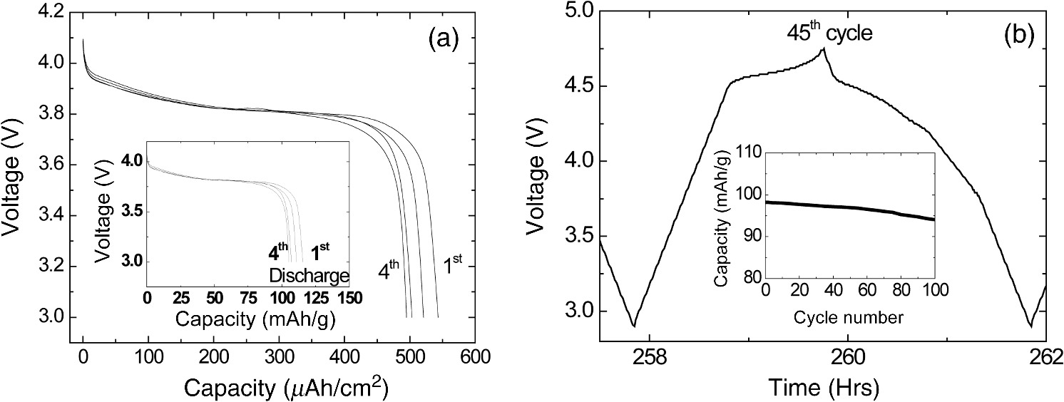
There has been continued interest in carbon-silicon composite systems and recently graphene–silicon systems have been reported as an alternative anode material for improved capacity. 28 PLD was employed to deposit amorphous Si thin films on a multilayer graphene (MLG) coated Ni foam substrate. 26 The graphene layers were grown by chemical vapor deposition and serve as an underlying adhesion and conducting layer for the a-Si anode. The electrochemical analysis of the cells based on the Si and Si-graphene anodes indicated that the Si-MLG cells displayed a stable capacity of . In contract, the pure Si cells showed high capacity during the first cycle ( ), but this capacity faded quickly during subsequent cycles. Thus, this combination of silicon and graphene offers an alternative route for addressing and alleviating volume expansion issues on Si anodes. Despite the benefits offered by the use of Si as anodes in Li-ion batteries, silicon’s structural and interfacial instability due to Li intercalation must be resolved before it can be used as a reliable anode material. The growth by PLD of Si layers over MLG (as shown by Radhakrishnan et al. 26 ) illustrates how this technique can be used to investigate the various types of Si/graphene structures with reduced cracking and delamination of the silicon anodes. Beyond this, PLD can also be used to generate more complex Si anodes comprising multilayer stacks, sandwiched structures, or layers with a controlled gradient in composition. Such nonuniform arrangements might help to reduce capacity fading and minimize cracking and delamination through improved handling of the large volume changes experienced, thus resulting in the improved stability of the silicon anodes. The electrochemical properties of thin-film anodes prepared by PLD are summarized in Table 2. Although significant improvement has been reported on the Si-based anode thin films, there is still room for further improvements, such as cycle life, high rate, capacity retention, and film thickness, in order to commercialize their applications. 2.3.Solid-State Thin-Film ElectrolyteOne of the key materials for fabricating thin-film Li-ion batteries is the identification of a suitable solid-state electrolyte, since the Li-ion batteries using highly flammable organic liquid electrolytes represent a safety issue. All-solid-state thin-film type Li-ion batteries using nonflammable solid electrolytes have attracted considerable attention due to their excellent potential for improving their safety and reliability. The PLD technique has been successfully employed in depositing various inorganic solid-state electrolytes, such as lithium phosphorous oxynitride (LIPON), (LVSO), , thio-LISICON, and films. 27 – 35 Table 3 lists the data from various electrolyte thin films prepared by PLD. Regarding the solid-state electrolyte, high ionic conductivity and low electronic conductivity are necessary for thin-film batteries. LIPON as a solid-state electrolyte has been successfully deposited by PLD. 30 It was observed that the ionic conductivity can be increased as the concentration of nitrogen was incorporated in the films by increasing the background gas pressure during deposition. 30 The Li-ion conductivity of various electrolyte thin films is between and . The high Li ion conductivity and low electron conductivity make these PLD grown solid-state thin-film electrolytes promising for developing all solid-state Li-ion microbatteries. Another key advantage of PLD in fabricating thin-film batteries is the flexibility for depositing all layers of the battery as discussed above. Thus, all-solid-state thin-film batteries can be fabricated by sequential PLD process. For example, Kuwata et al. 27 reported that thin-film microbatteries, consisting of cathode, LVSO solid electrolyte, and amorphous SnO anode, were fabricated by sequential PLD process. The amorphous LVSO electrolyte thin film provides a smooth and dense surface without any pinholes. This thin-film microbattery showed an initial discharge capacity of and 45% of its capacity was retained after 100 cycles at a constant current rate of between 0.01 and 3 V. In summary, PLD is a versatile technique for fabricating high-quality thin-films for numerous types of cathodes, anodes, and solid electrolytes for thin-film microbatteries. Since the films were crystallized at relatively low temperatures, highly textured and high purity cathode layers could be prepared by PLD. Amorphous silicon and silicon-graphene composite anodes were successfully prepared by PLD, while various solid-state thin-film electrolytes were fabricated by PLD with a high Li-ion conductivity. Finally, by applying sequential PLD growth, an all-solid-state-thin film microbattery has been demonstrated. Furthermore, from an applications point of view, the choice of substrate for thin-film microbatteries is highly relevant. Most of the cathode and anode thin films need to be deposited at elevated temperatures (500°C–600°C). Thus, it is very difficult to grow high quality electrode films on flexible plastic substrates. This is one of the limitations of thin-film batteries grown by physical vapor deposition techniques, such as e-beam and sputtering. However, since PLD grown films can crystallize at relatively low temperatures, it might be possible to grow active materials at reduced temperatures ( ) on flexible substrates, such as polyimide (Kapton). Although the PLD technique has been successfully employed for the deposition of thin-film batteries, this technique exhibits certain limitations when used for the fabrication of microbatteries. One of the shortcomings of thin-film electrodes grown by PLD is that the thickness of the electrode materials must be limited to less than a few microns in order to keep the internal cell resistance low. Because of this thickness limitation, the capacity of thin-film microbatteries as a function of active electrode area is not sufficient to operate many microelectronic devices. It might be possible to improve this thickness ceiling by co-depositing conductive carbon with the cathode and anode materials by alternatively exposing carbon and electrode targets during PLD. This co-deposition should enhance the conductivity in the electrodes, reduce the internal cell resistance, and accordingly allow for thicker electrodes. Another issue with the PLD is the difficulty in controlling the stoichiometry of volatile light elements such as lithium, as previously described in Sec. 2.1. This issue can be resolved by overcompensating the amount of lithium in the PLD target, the amount of which must be determined through a series of optimization deposition runs. Despite these limitations, PLD still merits consideration based on its ability to deposit layers with a graded composition for reducing structural and interfacial stability problems such as those encountered with silicon anodes as described in Sec. 2.2. 3.Laser-Induced Forward Transfer for Micropower SourcesLaser-induced forward transfer (LIFT) is a nozzle-free additive process, in which a controlled amount of complex material is transferred from a donor film to a receiving substrate upon interaction with a pulsed laser. 36 The concept of the LIFT process is simple, as is shown schematically in Fig. 2. It uses a pulsed laser to induce the transfer of material, such as a metal nanoink, from a donor substrate onto a receiving substrate. The donor substrate is typically a laser-transparent quartz wafer that is coated with the material of interest, referred to as the ribbon. The receiving substrate is located facing the donor substrate at a distance of tens of microns. Laser pulses propagate through the backside of the transparent ribbon and are absorbed by the donor film. When the incident laser is above the threshold energy, material is ejected from the ribbon and propelled toward the receiving substrate. Typical laser fluences used for printing battery materials vary from 10 to at the ribbon surface, depending on the thickness of the donor material. In general, the ribbon and receiving substrate are translated by a computer-controlled X-Y motion control system and the laser beam can be displaced by galvanometric scanning mirrors for fast pattern generation with the LIFT process. A charge coupled device camera positioned to view along the same optical axis as the focusing objective provides a real-time plan view of the transfer process and sample. Figure 2 shows a schematic illustration of the basic elements found in a LIFT system. In contrast to other film deposition and patterning techniques, LIFT processes do not necessarily require vacuum or clean-room environments and can be performed at ambient conditions. One of the advantages of this process is that due to its nozzle-free nature, LIFT is capable of printing patterns of 3-D pixels (or voxels) with nanoinks of much higher viscosity than that of inkjet printing, thus significantly reducing variations between patterns due to wetting and drying effects. 37 , 38 Despite its broad appeal given its simplicity, inkjet printing is limited to the transfer of low viscous, low solids loaded nanoparticle suspensions in order to avoid clogging of the dispensing nozzles. 39 Because of this limitation, printing of precise patterns by inkjet is very difficult given the variable behavior of fluids on different types of surfaces and their resulting instability due to wetting effects. 40 LIFT has been recently employed to print high viscosity pastes that reproduce the shape of the laser spot. 41 – 47 This process, referred to as laser-decal transfer, offers a new approach to direct-writing techniques, in which voxel shape and size become controllable parameters, allowing the generation of thin-film like structures for a wide range of applications, such as 3-D interconnects, metamaterials, free-standing structures, membranes, and circuit repair. The ability to modify the voxel shape and size according to the desired final pattern allows an increase in the resolution and speed of the printing process. In addition, a single laser pulse can print the complex shape in a one step process, reducing the processing time as well as avoiding problems related to the merging of multiple voxels as occurs with an inkjet printing 48 Therefore, printing shaped voxels increases the capabilities of LIFT as well as its potential degree of parallelization. 42 , 47 , 49 In addition, the size and shape of an incident laser beam can be dynamically controlled in real time with the use of a digital micromirror device, resulting in laser-printed functional materials with geometries identical to those of the projected beam. 42 , 47 Thus, this novel combination of the LIFT process and the digital micromirror devices of variable, structured voxels represent a dramatic improvement in the capabilities and throughput of laser direct-write processes. Another important feature of LIFT is that the deposited materials typically exhibit porous structures with high surface areas. These porous structures are an essential requirement for electrochemical devices since enhanced contact between the electrodes and the electrolyte leads to a better charge transfer, allowing a more complete utilization of the electrode materials. Thus, the LIFT techniques described here are ideally suited for fabricating the electrochemical device components required by most micropower systems, such as batteries, capacitors, and solar cells. 50 , 51 – 56 This section will show the use of LIFT techniques to process the active electrochemical materials for the fabrication of three representative micropower systems. The first micropower system is a rechargeable thick-film microbattery, the second is a Ruthenia-based planar ultracapacitor, and the third micropower system is an energy harvesting device (dye-sensitized solar cell). 3.1.Laser-Induced Forward Transfer of Thick-Film MicrobatteriesAlthough the thin-film Li and Li-ion microbatteries prepared by vapor deposition techniques provide high energy densities and long cycle life, 57 these vapor deposition processes are not able to simultaneously deposit the required composite components (active material, carbon, and electrolyte); as a result, the sputter-deposited cathode tin films (e.g., ) exhibit low electrical conductance because of the lack of conducting carbon in the films. In fact, the thickness of the electrode materials prepared by these techniques is typically limited to less than a few microns in order to keep cell resistance low. Because of this thickness limitation, the capacity per active electrode area of the thin-film microbatteries is not sufficient to operate many microelectronic devices. One approach to overcome the thickness limitation in thin-film microbatteries is to develop the thick-film electrodes using laser printing techniques, such as the LIFT process. The LIFT process has been successfully employed for printing thicker electrodes with much higher capacities per electrode area than the sputter-deposited thin-film electrodes. Details of the LIFT process have been described elsewhere. 41 – 56 In the electrode formulation, graphite (KS6) is added to improve the electric conductivity and carbon black (Super P) is added to increase the porosity in the electrode films. The polyvinylidene fluoride hexafluoropropylene (PVDF-HFP) is used as a binder to hold the electrode films onto current collectors. The dibasic ester is selected because it is a good solvent for the PVDF binder. The viscosity of the ink is controlled by the amount of the PVDF-HFP binder. The donor substrates were prepared by doctor blading a small amount of electrode ink onto a UV transparent quartz wafer using a wire coater (#5, Garner). Kim et al. 51 reported that the thickness of cathode thick films can be easily adjusted by varying the number of LIFT printing passes. As shown in Fig. 3(a), the thickness and mass of the cathode thick film increased linearly with the number of LIFT passes. The viscosity of the ink also affected the film thickness, i.e., for high viscosity inks, thicker films are deposited per LDW passes than with a lower viscosity inks. As the viscosity of the inks increases, the laser power required for their printing increases as well. This increase in laser power not only affects the printing resolution, but can also alter the materials suspended in the inks. Thus, optimization of the overall transfer process must also consider how the higher laser power affects the chemical and material properties of the ink components. The electrochemical properties of the laser-printed cathode thick films are highly dependent on the film thickness and the composition of the active electrode materials. Figure 3(b) shows the charge/discharge curves for Li-ion microbatteries with the laser-printed cathodes of different thicknesses ( ). Carbon was used as an anode layer and a polyolefin-based microporous membrane impregnated with a gel polymer electrolyte was used as a separator for these microbatteries. The microbatteries were assembled in a glove box and tested in ambient air at 25°C. The microbatteries are charged and discharged at a constant current of . As shown in Fig. 3(b), the discharge capacity per active electrode area is proportional to the cathode film thickness, indicating that the discharge capacity can be easily controlled by varying the cathode and anode thicknesses. The inset in Fig. 3(b) also shows the specific discharge capacity per cathode mass at the fifth cycle. Although the specific discharge capacity is lower for the microbattery with the thick cathode compared to the battery with the thick cathode due to a slightly higher internal resistance, a significantly large discharge capacity per unit area can be achieved for the thick cathode. These results indicate that the discharge capacity increases with the cathode thickness (up to 115 μm thick) due to their high surface area porous structure, allowing better ionic and electronic transport through the thick electrodes ( ) without any significant internal cell resistance. Fig. 3(a) cathode thickness and cathode mass as a function of the number of LIFT passes, (b) voltage versus discharge capacity per unit area and mass (inset) for packaged Li-ion microbatteries with cathodes of different thicknesses (35, 52, 70, and ). The MCMB was used as an anode. Batteries were charged and discharged at a constant current rate ( ) between 4.2 and 3 V. The active electrode area was . 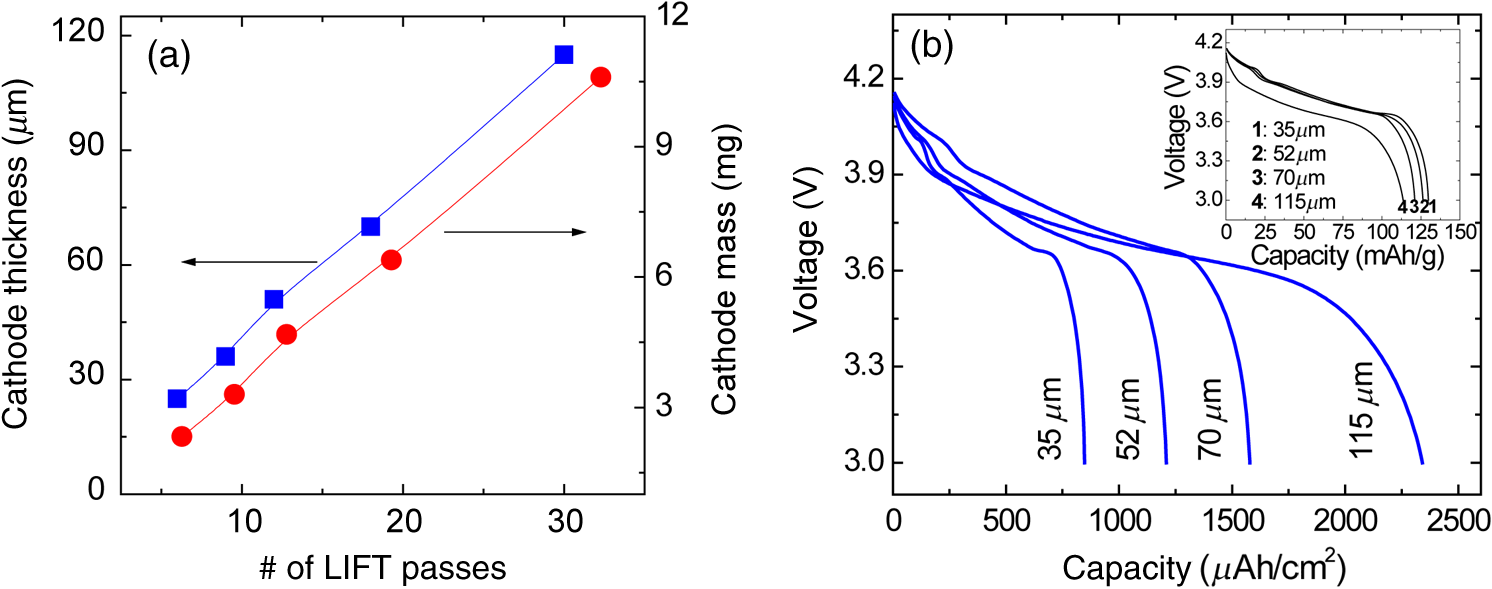 It is also reported that the thick-film Li-ion microbatteries prepared by LIFT exhibit a high discharge rate capability. 51 Figure 4 shows the areal energy and power densities for packaged thick-film microbatteries with three different cathode thicknesses (21, 45, and ). The slopes of the curves for all the cells are roughly parallel for power densities between 0.4 and , indicating that the thickness of the cathode is not a rate limiting factor for Li-ion transport during discharging. This implies that the energy per unit area can be increased simply by increasing the thickness of the electrodes without any significant internal resistance. The cell with the thick cathode produced a maximum power density of ( ) at a current density of . For all ranges of current densities, almost the same fraction of active material in all the cells is accessed for charge/discharge activities. These results confirm that the cathode thickness is not a rate limiting factor for the thick-film microbatteries prepared by LIFT. Fig. 4(a) Comparison of areal energy and power densities and (b) discharge capacity per cathode mass for packaged thick-film microbatteries with three cathode thicknesses (21, 45, and ).The active electrode area was . Microbatteries were charged at between 4.2 and 3 V. 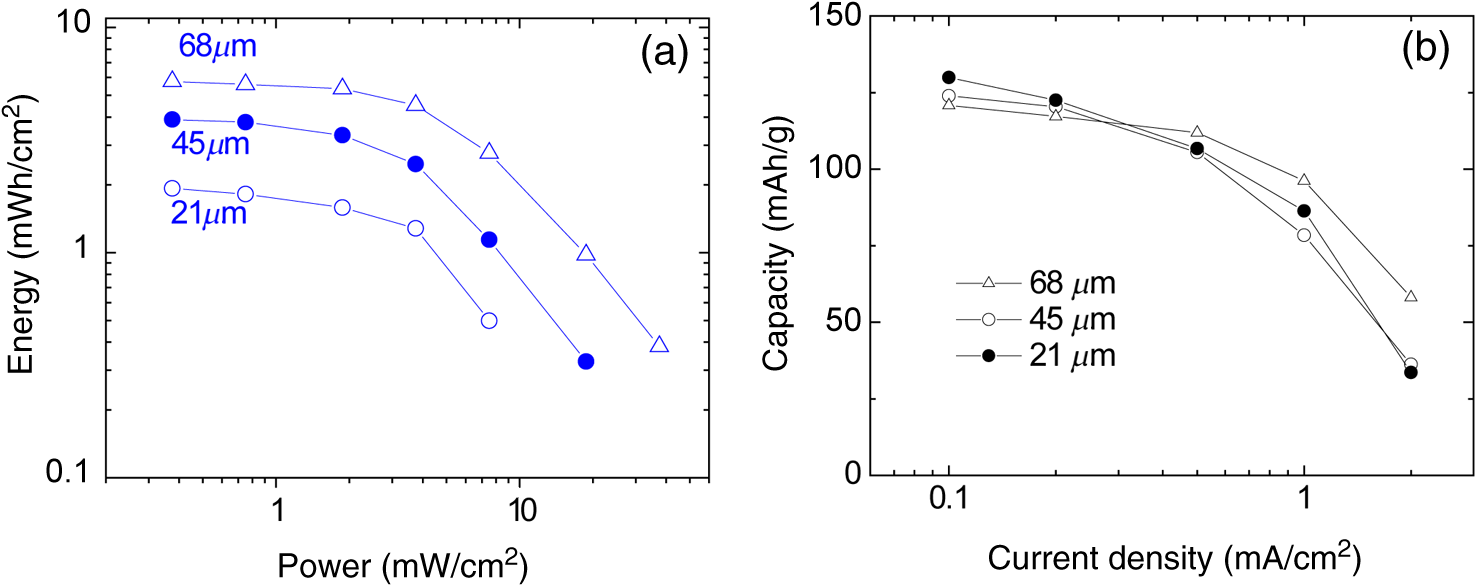 Current Li-ion battery systems are composed of a lithium metal (or a composite carbon) anode, a composite lithiated metal oxide cathode, and a lithium-ion conducting membrane with a liquid electrolyte. However, the use of the liquid electrolyte is limited by leakage and safety issues. In order to overcome these limitations, it is important to replace the liquid electrolyte with a solid-state polymer electrolyte since the volatility of the liquid electrolyte is no longer a concern. Our group at the Naval Research Laboratory, in Washington, DC, has developed a nanocomposite solid-polymer ionic liquid (nc-SPIL) as a solid-state electrolyte for the LIFT process. 50 , 52 , 53 The essential part of the nc-SPIL systems is that the laser-printed nc-SPIL membranes exhibited the proper electrochemical behavior for ionic liquids with a high ionic conductivity of , while maintaining the strength and flexibility of the PVD-HFP co-polymer matrix. Thus, they can serve as both the electrolyte and separator. 52 Figure 5(a) shows the first four cycles for a Li-ion microbattery fabricated with the nc-SPIL separator ( ), the -thick cathode, and the Li-metal anode. The battery was charged and discharged at a constant current density of ( rate) between 4.2 and 3 V. In Fig. 5(a), at the initial four cycles, the discharge capacity decreases with each cycle due to the formation of a solid electrolyte interface layer created at the interface between the electrodes and the gel polymer electrolyte due to the decomposition of the electrolyte solvent. However, after the fourth cycle, the microbattery had a coulomb efficiency of with a discharge capacity of , which is higher than the value of achieved for sputter-deposited Li microbatteries. 4 The LIFT process was employed to print sequential layers of the cathode ( ), nc-SPIL electrolyte, and anode (carbon) into a laser-micromachined pocket on a thin polyimide substrate (Kapton) to form an embedded all-solid-state Li-ion microbattery. 50 This microbattery was charged and discharged at a C/3 rate ( ) and exhibited an energy density of (or based on volume) corresponding to a specific energy of ( ). 3.2.Laser-Induced Forward Transfer of UltracapacitorsUltracapacitors are another type of electrochemical energy storage and power generation system typically used for load leveling and applications where a short burst of power is needed. The chemistry of this system involves two identical electrodes composed for example of a hydrous metal oxide whose electrochemical performance is sensitive to the processing temperature. 58 Arnold et al. 55 fabricated planar hydrous ruthenium oxide ultracapacitors using the LIFT process with significantly improved discharge behavior. The active ink was prepared by mixing hydrous ruthenium oxide powder and sulfuric acid electrolyte. The cells based on the laser-printed ruthenium oxide electrodes exhibited a linear charge/discharge response at constant current, indicating ideal capacitor behavior. These cells can be discharged at currents above 50 mA and can be connected in series and parallel combinations to yield the proper additive values. 59 3.3.Laser-Induced Forward Transfer of Dye-Sensitized Solar CellsThe LIFT technique has been used for depositing porous nanocrystalline (nc- ) films, which are incorporated for the fabrication of dye-sensitized solar cells (DSCs) 60 The anode in a typical DSC consists of a light-absorbing dye molecule attached to the surface of electrically connected nc- particles. The pores of the nc- film are filled with a liquid electrolyte (typically an redox couple). In this type of cell, the electrons generated by oxidation of the dye molecules are injected into the conduction band of the nc- film and transported to the external circuit through a transparent conducting oxide layer. On the cathode side, a metal catalyst enables the direct reduction of the electrolyte itself ( ), which subsequently reduces the dye molecules to their initial state. The schematic structure of a dye-sensitized solar cell is shown in Fig. 6(a). In the DSC system, the porous nanocrystalline microstructure of the layer with a high surface area is essential for achieving high efficiency because a large amount of dye can be adsorbed on the surface of the nc- particles resulting in an increased solar light absorption and an increased reacting interface per unit area. Thus, the LIFT process is ideally suited for generating these microstructures since the printed materials tend to form porous structures with the high surface areas. Fig. 6(a) Schematic cross section illustrating a dye-sensitized solar cell, (b) photograph of a packaged dye-sensitized solar cell fabricated with a laser-transferred nc- electrode. SEM micrographs showing, (c) the cross section, (d) the surface of a thick nc- layer printed by LIFT on FTO coated glass. The film was sintered at 450°C for 30 min, (e) current density versus voltage ( ) characteristics of dye-sensitized solar cells fabricated by laser-based techniques with different thicknesses of active layers under the light intensity of (AM 1.5 simulated solar illumination). The active cell area of all samples was . The dye solution was a ethanol solution of cis-bis(isothiocyanato) bis (2,2’-bipyridyl-4,4’-dicarboxylato)-ruthenium(II) (N3, Solaronix). The electrolyte was composed of 0.1M LiI, 0.5M DMPImI, 0.05M , 0.5M tert-butylpyridine in methoxyacetonitrile. 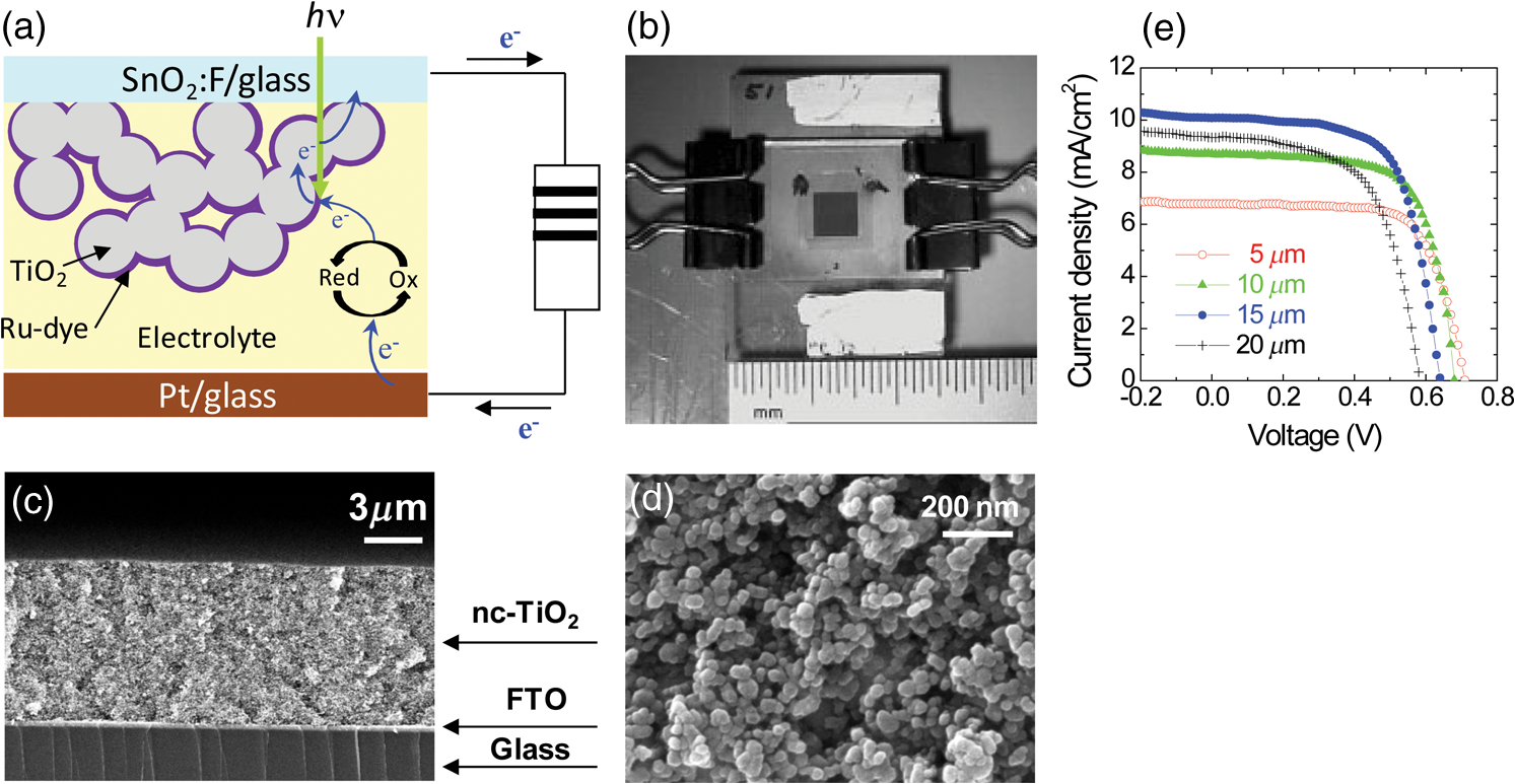 For the LIFT process of layers, the inks are made from water-based colloidal suspensions of nc- powders mixed with the organic additives. Mesoporous and nc- films are deposited onto fluorine doped tin oxide (FTO)-coated glass substrates by LIFT of these inks. 60 , 61 The transferred films are dried in air and sintered in the oven at 450°C for 30 min. Once the films are sintered, the electrode is soaked in the dye solution in order to coat the surface. Finally, the completed cells are assembled and sealed using a Surlyn gasket to separate the anode and cathode layers and to provide a reservoir for the electrolyte [see Fig. 6(b)]. The thickness and mass of the nc- layers can be easily controlled by varying the number of LIFT passes over the substrate. By looking at a cross-sectional SEM in Fig. 6(c), it is clear that no interfacial gaps are formed between the nc- layers because the printed material remains in the form of a viscous fluid after the LIFT transfer. As shown in Fig. 6(d), the transferred materials maintain a homogeneously distributed network of particles with a high degree of porosity, consistent with a high surface area structure. The 3-D network of interconnected nanoparticles enables good electron conduction, while the high surface area structure maximizes the amount of dye adsorbed on the surface of the particles. Both properties are essential for the fabrication of efficient dye-sensitized solar cells. Figure 6(e) shows the current density ( ) versus voltage ( ) characteristics for several dye sensitized solar cells with various thicknesses of laser-printed nc- layers. The initial increase in the short-circuit current density ( ) with the nc- film thickness can be related to the increased surface area of the films and concomitantly the increased amount of dye molecules. Although the thicker films allow for more adsorbed dye molecules and would be expected to produce higher photocurrents, in practice, thick nc- films also contain a large number of defect/recombination sites resulting in an overall decrease in the cell operational characteristics. Because of this, the thickness of the nc- films must be optimized for simultaneously improving both and parameters. The cell based on the optimized nc- film ( ) exhibited a current density of , open circuit voltage of 0.65 V, a fill factor of 0.69, and a light power conversion efficiency of . The conversion efficiency is comparable to those reported earlier for analogous cells fabricated with commercial powders (P25) using traditional screen printing techniques. 62 , 63 The measurements of these cells were performed in a glove box. However, the cells sealed with a thermally cured polymer (Surlyn) showed consistent cell performance after sitting on the desk in air for several months. Thus, the cells showed excellent stability in air after sealing. Despite the advantages of laser printed electrodes for microbatteries, ultracapacitors and dye-sensitized solar cells are still far from optimized. Much work is needed to develop appropriate strategies to seal and package the printed multilayer structures while minimizing the delamination of the electrode layers from the metallic current collectors. The challenge remains to develop packaging approaches that achieve a reliable seal without resulting in an excessive increase in weight and volume, as is the case with metal sealed coin cell batteries, which negate the benefits of the small footprint occupied by the active materials. In this sense, the development of printed embedded microbatteries solves this issue by using the substrate itself as the packaging. The concept of an embedded microbattery made by laser printing was first demonstrated by Sutto et al. 50 4.Laser Surface Processing for Materials ModificationAnother versatile capability of laser-related processing techniques is to modify the surface properties of the active materials in order to improve their performance for power source applications. Three examples of laser materials processing for improving their properties in power sources are discussed. One is the laser sintering process to form a 3-D network of particles for dye-sensitized solar cells. The second is the laser structuring process used to generate the electrodes with 3-D architectures for Li-ion microbatteries, and the third is used to reduce the graphitic oxide layers for ultracapacitor applications. 4.1.Laser Sintering of Nanocrystalline-TiO2 ElectrodesIn order to prepare the mesoporous working electrodes in a DSC, the organic additives, typically a poly(ethylene glycol)-based surfactant, must be removed after printing by ashing and then sintering. The presence of these additives is necessary for the formation of a viscous colloidal suspension that is essential in building crack-free thick films with an increased porosity after sintering. In order to maximize the device efficiency, the printed electrodes must be sintered at relatively high temperatures ( ) to remove the organic additives and to form an electrically connected nanostructure network within the mesoporous electrode. Due to the high sintering temperature treatment, most of the work on DSCs has been limited to substrates that can withstand high temperatures, such as glass and stainless steel. Considering manufacturing costs, flexibility, and safety issues, the use of plastic substrates can offer many advantages over glass substrates because the DSC devices based on plastic substrates would be cheaper, lighter, and thinner than the DSC devices on glass substrates. For this reason, a low temperature sintering process would be highly useful in the fabrication of electrodes. By using the same laser from the LIFT apparatus in a quasi-cw mode rather than a pulsed mode, it is possible to remove the high temperature sintering step from the overall DSC fabrication processes. 61 Figure 7 shows the SEM cross-sectional micrographs from laser-printed electrodes on FTO-coated glass substrates before and after the laser treatment. Laser-printed electrodes were first heat treated at 100°C to remove the excess organic solvent from the paste. This low temperature heating was not sufficient to remove the organic additives from the printed films, but it was sufficient to form the clusters (100–200 nm in diameter) of nanoparticles bound together by the dried organic additives [see Fig. 7(a)]. Such clusters are not well suited to form the electronically connected nanostructure network required for the proper operation of DSCs. Figure 7(b) shows that the laser sintering process is capable of removing the organic additives from the electrode and forming an electrically connected network structure in the nc- electrode. A detailed explanation can be found in Ref. 61. Typical laser sintering at IR wavelengths is insufficient for due to its large bandgap (anatase, 3.2 eV), and, thus, low absorption. However, the same UV source ( ) that was used for the LIFT of the nc- inks was successfully employed for the laser sintering of electrodes. Fig. 7Cross-sectional SEM micrographs of nc- electrodes prepared on FTO-coated glass substrates. Both samples were first dried in an oven at 100°C for 18 h. Image (a) was taken before laser sintering, while (b) was obtained after laser sintering at . 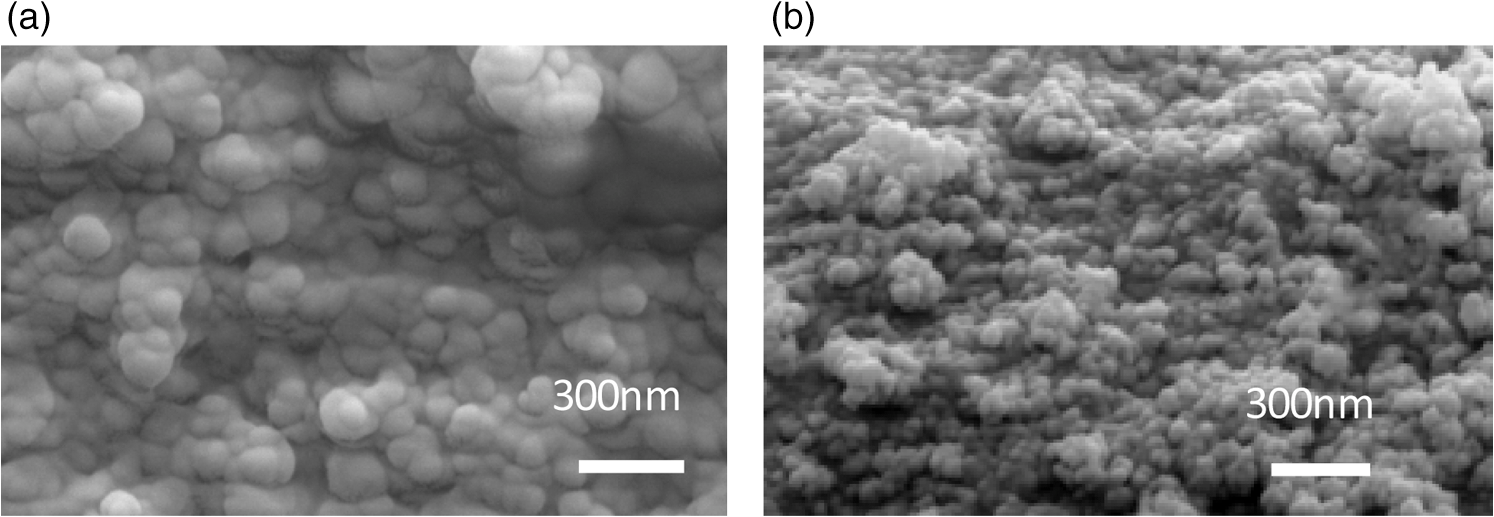 To date, the power conversion efficiency of the device based on the laser sintered nc- electrode is 1.8%, which is more than a twofold improvement from that of the device based on a nonlaser-sintered electrode (0.7%). However, the 1.8% efficiency is still low in comparison to the standard cell (4.7%) fabricated with a high temperature (450°C for 1 h) sintered nc- electrode, indicating that further improvements are required. This low efficiency might be related to the insufficient necking of nc- particles, which leads to poor electron transport. However, this insufficient necking problem might be improved by further optimization of the laser sintering conditions. These preliminary results indicate that the laser sintering technique is a promising approach for the fabrication of nc- electrodes, especially for plastic DSCs. An advantage of this approach is that it allows both the transfer of the ink and in situ sinter of the mesoporous nc- electrodes using the same UV laser, thus, simplifying the processing steps required for fabricating DSCs at low temperatures. Furthermore, there is still ample room for improvement in this process by further optimization of the laser sintering conditions such as laser beam size, power intensity, and translation speed. 61 In addition, this laser sintering process has also been employed to fabricate transparent conducting indium tin oxide (ITO) electrodes, which are widely used in photovoltaic devices such as solar cells and touch-screen displays. 64 A dispersion of ITO nanoparticles was printed on the glass substrate by the LIFT process and then annealed at 450°C in ambient air on a hot plate. However, due to the extremely high melting temperature of the ITO particles ( ), annealing at 450°C was not enough to form a fully dense ITO film. Instead, the irradiation from an excimer laser was successfully applied to the surface of the printed ITO layer, resulting in an improved electrical conductivity ( ). 65 4.2.Laser Structuring of Thick-Film ElectrodesAnother important laser materials’ processing application is the surface structuring of electrodes in microbatteries. Recently, 3-D architectures of microbatteries have been proposed to enhance the power density while maintaining the high energy density of microbattery systems. 66 – 70 An excimer laser has been successfully employed to precisely ablate the cathode materials, such as lithium cobalt oxide ( ) 54 , 71 lithium manganese oxide, 72 and tin oxide 73 to form the 3-D architectures with improved lithium-ion diffusion pathways. Kim et al 54 reported that the laser-printed thick films were further treated with the laser structuring process using a KrF excimer laser in order to form the 3D architectures on them. Figure 8 shows the cycling test of the unstructured and the laser-structured cathode films at a constant C/5 rate between 4.2 and 3 V with Li-metal anode and liquid electrolyte of 1M in ethylene carbonate/dimethyl carbonate. Although the unstructured cathode film produces slightly higher starting discharge capacities, the laser-structured cathode exhibits improved capacity retention. After 100 cycles, the laser structured cathode showed a capacity of , which was two times higher than that of the unstructured cathode. This improved capacity retention is due to the improved Li-ion diffusion rate due to the 3D architectures of the cathode. 74 Fig. 8(a) Cycling performance of unstructured and laser-structured cathode films. A laser fluence of , laser repetition rate of 300 Hz and 250 laser pulses were focused over an area of for the laser structuring process. SEM images of (b) unstructured and (c) laser-structured films. A laser fluence of , laser repetition rate of 300 Hz and 250 laser pulses were used for laser structuring.  In order to achieve high processing speeds to scale-up the laser structuring process, lasers capable of delivering ultrashort pulses at very high repetition rates are required. This can be achieved by using high power femtosecond (fs) lasers. The use of fs laser pulses minimizes damage to the cathode material near the ablated regions resulting in very uniform channel structures, while the mass loss due to the material removed during the process is of the order of 15 wt%. For example, a fs laser structuring process has been reported to form the 3D microgrids in laser-printed electrodes without thermal impact or damage of the active material. 75 , 76 Laser-printed cathodes are first calendered and then laser structured using fs-laser ablation. Battery tests confirmed that the 3D microgrids in calendered/laser-structured cathodes exhibit improved discharge capacity retention. In this work, the overall improvement in electrochemical cell performance was achieved by using a combination of laser-printing, calendaring, and fs-laser structuring processes. So far, the laser structuring process has been applied to several cathode materials ( , , and ) with various thickness ranges (3 to ). Currently, cathode materials are under investigation as a function of high aspect ratio 3-D grid structures. In all these various cathode systems, the laser structuring into the 3-D topographies with a high aspect ratio resulted in significantly improved battery performance as compared to traditional planar thick-film layers. In addition, further process improvements can be achieved by optimizing the laser parameters, such as laser fluence, and translation speed, as well as optimizing the aspect ratio. 4.3.Laser Reduction of Graphite Oxides for Electrochemical CapacitorsAnother laser materials’ processing application is the laser reduction of graphite oxide (GO) for electrochemical capacitors. 77 – 80 Recently, graphite oxides have been reduced by laser radiation with an improved electrical conductivity and the reduced graphite oxides (RGO) have been proposed to enhance energy density while maintaining the high power density of electrochemical capacitor systems. 77 , 78 Gao et al. 78 have demonstrated that graphite oxide (GO) becomes a strong anisotropic ionic conductor when water is entrapped during the laser reduction process. The hydrated GO with 16 wt% water content exhibited of ionic conductivity for the in-plane structure. The active RGO electrode, formed from hydrated GO after laser heating, is porous due to the gases produced from the decomposition of the functional group and water under localized laser heating. The cyclic stability tests performed on the sandwiched supercapacitor devices showed an drop in the capacitance after 10,000 cycles. This drop in the capacitance could be related to water loss in the device. The capacitance doubled when the same device was kept at ambient conditions for a week after a long cycling test. The electrochemical properties, including capacitance, ionic conductivity, energy density and power density, are summarized in Table 4. 78 Table 4Electrochemical properties of laser-reduced graphite oxide (RGO), laser-scribed graphene (LSG), and their electrochemical capacitors.
El-Kady et al. 77 used the laser diode from a standard LightScribe DVD optical drive for the direct laser reduction of GO films to graphene. Initially, a thin film of GO dispersed in water was drop cast onto a flexible substrate. Irradiation of the film with an infrared laser reduces the GO to laser-scribed graphene (LSG). The resulting LSG films showed excellent conductivity ( ), which is significantly higher than that of the activated carbon ( ). This LSG-electrochemical capacitor showed a nearly rectangular cyclic voltammetry shape at a scan rate of 1000 mVs in aqueous 1.0 M solution, indicating ideal capacitor behavior. The areal capacitance of the LSG capacitor was calculated to be at . This capacitor also showed a very high rate capability while still maintaining a capacitance of greater than even at . Furthermore, this capacitor showed excellent cyclic stability with 96% of capacitance retention of this initial capacitance after 10,000 cycles. 77 The electrochemical properties of the LSG-electrochemical capacitor are summarized in Table 4. Laser-reduced graphene was also used as a high power anode material for Li-ion batteries. 81 GO diluted in deionized water was vacuum-filtered through a pore size Whartman Anodisc filter to prepare GO papers ( thick). A CW laser ( ) with a laser spot size of was used to reduce the GO. The laser operated at 4.8W was rastered in a pattern with a line spacing of over 50-mm diameter GO paper, converting to graphene in a single scan. This laser-reduced graphene paper showed an expanded structure such as wide cracks, pores, and intersheet voids as compared to that of GO paper. This expanded structure enables greater access for Li-ions to active intercalation sites. The laser-reduced graphene anodes were assembled in a two-electrode coin cell (2032) using Li-foil as the counter electrode, a Celgard 2340 polypropylene membrane as the separators, and 1 M in mixture in EC:DEC as the electrolyte. The laser-reduced graphene anodes delivered a at charge/discharge rates of 40°C, providing . 81 Laser surface modification and sintering processes are not well suited for treating very thick layers. Their effectiveness is directly related to the laser absorption depth which depends on the material and applied laser wavelength. Thus, for batteries and other power source materials, the absorption depth is of the order of a few microns at best, which means that these processes are only effective for very thin layers and must be applied multiple times if thicker structures are planned. Finally, since the laser beam illuminates a relatively small area, treating an entire sample takes time. On the other hand, these laser processes allow the high temperature treatment of layers deposited on plastic substrates without damaging the substrates underneath, thus making possible the formation of crystalline rather than amorphous electrode layers without having to heat the substrate on which they were deposited. 5.ConclusionsWe have reviewed various laser-based processing techniques, such as PLD, LIFT, and laser surface modification, for the fabrication of energy storage and power generation devices. The PLD technique has been shown to deposit numerous types of cathodes, anodes, and solid electrolyte for thin-film microbatteries and by applying sequential PLD, all-solid-state thin-film microbatteries have been successfully fabricated. The LIFT technique has been shown to print complex materials with a high porosity, which is ideal for the fabrication of micropower sources, such as thick-film batteries and metal oxide-based solar cells. Finally, the laser is a flexible tool that can modify the surface properties of active materials by sintering, structuring, or reducing their oxygen content in order to improve their electrochemical performance by enhancing the electrodes 3-D networked structure, increasing their overall active surface or enhancing their ionic and electric conductivity, respectively. As indicated in the Introduction, laser-based processes have been recognized as practical approaches to integrate micropower sources with microdevices. In principle, these laser-based processes can be used at the beginning, during, or after the fabrication of a device. For example, with PLD the growth of thin films would most likely take place at the beginning of the device fabrication steps, since the films will have to be patterned after deposition and other steps will be required before a device can be produced. On the other hand, the laser printing processes can be applied at any point during fabrication, even after the device has been completed, since LIFT is additive and nonlithographic in nature. Thus, laser printing of a microbattery for a particular device could take place after the device is already manufactured, allowing the embedding of micropower sources into the existing devices. Finally, laser surface modification could be applied at any stage of the fabrication process and can be targeted to only a specific region of a structure or device, which opens a wide range of possibilities. This flexibility and adaptability make the use of laser-based processing techniques for micropower sources highly applicable for solving the challenge of developing fully integrated autonomous microelectronics. AcknowledgmentsThis work was supported by the Office of Naval Research (ONR) through the Naval Research Laboratory Basic Research Program. Special thanks to Dr. Mike Ollinger for his help in the fabrication of embedded microbatteries and nc-SPIL membranes, Ray Auyeung for his help with laser annealing of layers, and Dr. Johannes Pröll and Dr. Wilhelm Pfleging of the Karlsruhe Institute of Technology and the Karlsruhe Nano Micro Facility (KNMF), for laser structuring. References
H. Mazor
et al.
,
“Electrophoretic deposition of lithium iron phosphate cathode for thin-film 3D-microbatteries,”
J. Power Sources, 198 264
–272
(2012). http://dx.doi.org/10.1016/j.jpowsour.2011.09.108 0378-7753 Google Scholar
C. Wang
et al.
,
“Buckled, stretchable polypyrrole electrodes for battery applications,”
Adv. Mat., 23
(31), 3580
–3584
(2011). http://dx.doi.org/10.1002/adma.201101067 0935-9648 Google Scholar
K. Sun
et al.
,
“3-D printing of interdigitated Li-ion microbattery architectures,”
Adv. Mat., 25
(33), 4539
–4543
(2013). http://dx.doi.org/10.1002/adma.v25.33 0935-9648 Google Scholar
J. Bates
et al.
,
“Preferred orientation of polycrystalline LiCoO2 films,”
J. Electrochem. Soc., 147
(1), 59
–70
(2000). http://dx.doi.org/10.1149/1.1393157 0013-4651 Google Scholar
P. B. Koeneman
I. J. Busch-Vishniac
K. L. Wood
,
“Feasibility of micro power supplies for MEMS,”
J. Microelectromech. Sys., 6
(4), 355
–362
(1997). http://dx.doi.org/10.1109/84.650133 1057-7157 Google Scholar
H. Kim
et al.
,
“Laser processing of nanocrystalline TiO2 for dye-sensitized solar cells,”
Appl. Phys. Lett., 85
(3), 464
–466
(2004). http://dx.doi.org/10.1063/1.1772870 0003-6951 Google Scholar
R. Eason
, Pulsed Laser Deposition of Thin Films, Wiley, New York
(2006). Google Scholar
D. B. Chrisey
G. K. Hubler
, Pulsed Laser Deposition of Thin Films, Wiley, New York
(1994). Google Scholar
C. R. Phipps
, Laser Ablation and its Applications, Springer, New York
(2006). Google Scholar
H. Kim
et al.
,
“Electrical, optical and structural properties of indium tin oxide thin films for organic light-emitting devices,”
J. Appl. Phys., 86
(11), 6451
–6461
(1999). http://dx.doi.org/10.1063/1.371708 0021-8979 Google Scholar
H. Kim
et al.
,
“Effect of aluminum doping on zinc oxide thin films grown by pulsed laser deposition for organic light emitting diodes,”
Thin Solid Films, 377–378 798
–802
(2000). http://dx.doi.org/10.1016/S0040-6090(00)01290-6 0040-6090 Google Scholar
H. Kim
et al.
,
“Indium tin oxide thin films grown on flexible plastic substrates for organic light-emitting devices,”
Appl. Phys. Lett., 79
(3), 284
–286
(2001). http://dx.doi.org/10.1063/1.1383568 0003-6951 Google Scholar
C. Julien
et al.
,
“Growth of
thin films by pulsed laser deposition and their electrochemical properties in lithium microbatteries,”
Mat. Sci. Eng. B, 72
(1), 36
–46
(2000). http://dx.doi.org/10.1016/S0921-5107(99)00598-X 0921-5107 Google Scholar
Y. Iriyama
et al.
,
“Preparation of c-axis oriented thin films of LiCoO2 by pulsed laser deposition and their electrochemical properties,”
J. Power Sources, 94
(2), 175
–182
(2001). http://dx.doi.org/10.1016/S0378-7753(00)00580-2 0378-7753 Google Scholar
H. Xia
L. Lu
G. Ceder
,
“Substrate effect on the microstructure and electrochemical properties of LiCoO2 thin films grown by PLD,”
J. Alloys Compd., 417
(1–2), 304
–310
(2006). http://dx.doi.org/10.1016/j.jallcom.2005.09.065 0925-8388 Google Scholar
W. S. Kim
,
“Characteristics of LiCoO2 thin film cathodes according to the annealing ambient for the post-annealing process,”
J. Power Sources, 134
(1), 103
–109
(2004). http://dx.doi.org/10.1016/j.jpowsour.2004.02.035 0378-7753 Google Scholar
T. Matsumura
et al.
,
“Electrical performances for preferred oriented PLD thin-film electrodes of LiNi0.8Co0.2O2, LiFePO4 and LiMn2O4
,”
Solid State Ionics, 179
(35–36), 2011
–2015
(2008). http://dx.doi.org/10.1016/j.ssi.2008.06.015 0167-2738 Google Scholar
F. Simmen
et al.
,
“The influence of lithium excess in the target on the properties and compositions of
,”
Appl. Phys. A., 93
(3), 711
–716
(2008). http://dx.doi.org/10.1007/s00339-008-4701-1 0947-8396 Google Scholar
G. X. Wang
et al.
,
“Physical and electrochemical characterization of LiNi0.8Co0.2O2 thin-film electrodes deposited by laser ablation,”
J. Power Sources, 97–98 298
–302
(2001). http://dx.doi.org/10.1016/S0378-7753(01)00664-4 0378-7753 Google Scholar
H. Xia
L. Lu
Y. S. Meng
,
“Growth of layered
thin films by pulsed laser deposition for application in microbatteries,”
Appl. Phys. Lett., 92
(1), 011912
(2008). http://dx.doi.org/10.1063/1.2829605 0003-6951 Google Scholar
C. V. Ramana
K. Zaghib
C. M. Julien
,
“Pulsed-laser deposited LiNi0.8Co0.15Al0.05O2 thin films for application in microbatteries,”
Appl. Phys. Lett., 90
(2), 021916
(2007). http://dx.doi.org/10.1063/1.2430933 0003-6951 Google Scholar
H. Xia
L. Lu
,
“Texture effect on the electrochemical properties of LiCoO2 thin films prepared by PLD,”
Electrochim. Acta, 52
(24), 7014
–7021
(2007). http://dx.doi.org/10.1016/j.electacta.2007.05.019 0013-4686 Google Scholar
J. D. Perkins
et al.
,
“ LiCoO2 and
thin film cathodes grown by pulsed laser ablation,”
J. Power Sources, 81–82 675
–679
(1999). http://dx.doi.org/10.1016/S0378-7753(99)00266-9 0378-7753 Google Scholar
Z. G. Lu
M. F. Lo
C. Y. Chung
,
“Pulsed laser deposition and electrochemical characterization of LiFePO4-C composite thin films,”
J. Phyc. Chem. C, 112
(17), 7069
–7078
(2008). 0022-3654 Google Scholar
B. Yan
et al.
,
“Li-rich thin film cathode prepared by pulsed laser deposition,”
Sci. Rep., 3 33321
–5
(2013). 2045-2322 Google Scholar
G. Radhakrishnan
et al.
,
“Pulsed laser deposited Si on multilayer graphene as anode material for lithium ion batteries,”
APL Mater., 1
(6), 0621031
–6
(2013). http://dx.doi.org/10.1063/1.4834735 2166-532X Google Scholar
N. Kuwata
et al.
,
“Thin-film lithium-ion battery with amorphous solid electrolyte fabricated by pulsed laser deposition,”
Electrochem. Commum., 6
(4), 417
–421
(2004). http://dx.doi.org/10.1016/j.elecom.2004.02.010 1388-2481 Google Scholar
U. Kasavajjula
C. Wang
A. J. Appleby
,
“Nano- and bulk-silicon-based insertion anodes for lithium-ion secondary cells,”
J. Power Sources, 163
(2), 1003
–1039
(2007). http://dx.doi.org/10.1016/j.jpowsour.2006.09.084 0378-7753 Google Scholar
J. H. Ryu
et al.
,
“Failure modes of silicon powder negative electrode in lithium secondary batteries,”
Electrochem. Solid-State Lett., 7
(10), A306
–A309
(2004). http://dx.doi.org/10.1149/1.1792242 1099-0062 Google Scholar
S. Zhao
Z. Fu
Q. Qin
,
“A solid-state electrolyte lithium phosphorus oxynitride film prepared by pulsed laser deposition,”
Thin Solid Films, 415
(1–2), 108
–113
(2002). http://dx.doi.org/10.1016/S0040-6090(02)00543-6 0040-6090 Google Scholar
S. Zhao
Q. Qin
,
“Li-V-Si-O thin film electrolyte for all-solid-state Li-ion battery,”
J. Power Sources, 122
(2), 174
–180
(2003). http://dx.doi.org/10.1016/S0378-7753(03)00400-2 0378-7753 Google Scholar
J. Kawamura
et al.
,
“Preparation of amorphous lithium ion conductor thin films by pulsed laser deposition,”
Solid State Ionics, 175
(1–4), 273
–276
(2004). http://dx.doi.org/10.1016/j.ssi.2004.05.034 0167-2738 Google Scholar
N. Ohta
et al.
,
“Solid electrolyte, thio-LISICON thin film prepared by pulsed laser deposition,”
J. Power Sources, 146
(1–2), 707
–710
(2005). http://dx.doi.org/10.1016/j.jpowsour.2005.03.062 0378-7753 Google Scholar
Y. Sakurai
et al.
,
“Preparation of amorphous Li4SO4-Li3PO4 thin films by pulsed laser deposition for all-solid-state lithium secondary batteries,”
Solid State Ionics, 182
(1), 59
–63
(2011). http://dx.doi.org/10.1016/j.ssi.2010.12.001 0167-2738 Google Scholar
A. Sakuda
et al.
,
“Preparation of highly lithium-ion conductive 80Li2S-20P2O5 thin-film electrolytes using pulsed laser deposition,”
J. Am. Ceram. Soc., 93
(3), 765
–900
(2010). http://dx.doi.org/10.1111/jace.2010.93.issue-3 0002-7820 Google Scholar
C. B. Arnold
P. Serra
A. Piqué
,
“Laser direct-write techniques for printing of complex materials,”
MRS Bull., 32
(1), 23
–31
(2007). http://dx.doi.org/10.1557/mrs2007.11 0883-7694 Google Scholar
A. Piqué
et al.
,
“Digital microfabrication by laser decal transfer,”
J. Laser Micro/Nanoeng., 3
(3), 163
–169
(2008). http://dx.doi.org/10.2961/ 1880-0688 Google Scholar
M. Duocastella
et al.
,
“Optimization of laser printing of nanoparticles suspensions for microelectronic applications,”
Appl. Phys. A-Mater., 106
(3), 471
–478
(2012). http://dx.doi.org/10.1007/s00339-011-6751-z 0947-8396 Google Scholar
P. Calvert
,
“Inkjet printing for materials and devices,”
Chem. Mater., 13
(10), 3299
–3305
(2001). http://dx.doi.org/10.1021/cm0101632 0897-4756 Google Scholar
H. Kang
D. Soltman
V. Subramanian
,
“Hydrostatic optimization of inkjet-printed films,”
Langmuir, 26
(13), 11568
–11573
(2010). http://dx.doi.org/10.1021/la100822s 0743-7463 Google Scholar
A. Piqué
et al.
,
“Laser transfer of reconfigurable patterns with a spatial light modulator,”
Proc. SPIE, 8608 86080K
(2013). http://dx.doi.org/10.1117/12.2005345 0277-786X Google Scholar
A. Piqué
et al.
,
“Laser forward transfer of functional materials for digital fabrication of microelectronics,”
J. Imaging Sci. Technol., 57
(4), 040101
(2013). http://dx.doi.org/10.2352/J.ImagingSci.Technol.2013.57.4.040404 1062-3701 Google Scholar
J. Wang
et al.
,
“Three-dimensional printing of interconnects by laser direct-write of silver nanopastes,”
Adv. Mater., 22
(40), 4462
–4466
(2010). http://dx.doi.org/10.1002/adma.v22:40 0935-9648 Google Scholar
H. Kim
et al.
,
“Laser printing of conformal and multi-level 3D interconnects,”
Appl. Phys. A-Mater., 113
(1), 5
–8
(2013). http://dx.doi.org/10.1007/s00339-013-7909-7 0947-8396 Google Scholar
H. Kim
et al.
,
“Fabrication of terahertz metamaterials by laser printing,”
Opt. Lett., 35
(23), 4039
–4041
(2010). http://dx.doi.org/10.1364/OL.35.004039 0146-9592 Google Scholar
R. C. Y. Auyeung
et al.
,
“Laser decal transfer of freestanding microcantilevers and microbridges,”
Appl. Phys. A-Mater., 97
(3), 513
–519
(2009). http://dx.doi.org/10.1007/s00339-009-5433-6 0947-8396 Google Scholar
R.C. Y. Auyeung
et al.
,
“Laser forward transfer based on a spatial light modulator,”
Appl. Phys. A-Mater., 102
(1), 21
–26
(2011). http://dx.doi.org/10.1007/s00339-010-6054-9 0947-8396 Google Scholar
D. Soltman
et al.
,
“Methodology for inkjet printing of partially wetting films,”
Langmuir, 26
(19), 15686
–15693
(2010). http://dx.doi.org/10.1021/la102053j 0743-7463 Google Scholar
S. A. Mathews
et al.
,
“High-speed video study of laser-induced forward transfer of silver nano-suspensions,”
J. Appl. Phys., 114
(6), 064910
(2013). http://dx.doi.org/10.1063/1.4817494 0021-8979 Google Scholar
T. E. Sutto
et al.
,
“Laser transferable polymer-ionic liquid separator/electrolytes for solid-state rechargeable lithium-ion microbatteries,”
Electrochem. Solid-State Lett., 9
(2), A69
–A71
(2006). http://dx.doi.org/10.1149/1.2142158 1099-0062 Google Scholar
H. Kim
R. C. Y. Auyeung
A. Piqué
,
“Laser-printed thick-film electrodes for solid-state rechargeable Li-ion microbatteries,”
J. Power Sources, 165
(1), 413
–419
(2007). http://dx.doi.org/10.1016/j.jpowsour.2006.11.053 0378-7753 Google Scholar
M. Ollinger
et al.
,
“Laser direct-write of polymer nanocomposite,”
Appl. Sur. Sci., 252
(23), 8212
–8216
(2006). http://dx.doi.org/10.1016/j.apsusc.2005.10.041 0169-4332 Google Scholar
M. Ollinger
et al.
,
“Laser printing of nanocomposite solid-state electrolyte membranes for Li micro-batteries,”
J. Micro/Nanoeng., 1
(2), 102
–105
(2006). Google Scholar
H. Kim
et al.
,
“Laser-printed and processed LiCoO2 cathode thick films for Li-ion microbatteries,”
J. Micro/Nanoeng., 7
(3), 320
–325
(2012). Google Scholar
C. B. Arnold
et al.
,
“Direct writing of planar ultracapacitor by laser forward transfer processing,”
Proc. SPIE, 4637 353
–60
(2002). http://dx.doi.org/10.1117/12.470641 0277-786X Google Scholar
R.C. Wartena
et al.
,
“Li-ion microbatteries generated by a laser direct-write method,”
J. Power Sources, 126
(1–2), 193
–202
(2004). http://dx.doi.org/10.1016/j.jpowsour.2003.08.019 0378-7753 Google Scholar
N. J. Dudney
Y.-I. Jang
,
“Analysis of thin film lithium batteries with cathodes of 50 nm to 4 μm thick LiCoO2
,”
J. Power Sources, 119–121 300
–304
(2003). http://dx.doi.org/10.1016/S0378-7753(03)00162-9 0378-7753 Google Scholar
D. A. McKeown
et al.
,
“Structure of hydrous ruthenium oxides: implications for charge storage,”
J. Phys. Chem. B, 103
(23), 4825
–4832
(1999). http://dx.doi.org/10.1021/jp990096n 1520-6106 Google Scholar
C. B. Arnold
et al.
,
“Direct-write planar microultracapacitors by laser engineering,”
J. Electrochem. Soc., 150
(5), A571
–A575
(2003). http://dx.doi.org/10.1149/1.1563650 0013-4651 Google Scholar
H. Kim
et al.
,
“Laser processing of nanocrystalline TiO2 for dye-sensitized solar cells,”
Appl. Phys. Lett., 85
(3), 464
–466
(2004). http://dx.doi.org/10.1063/1.1772870 0003-6951 Google Scholar
H. Kim
et al.
,
“Laser-sintered mesoporous TiO2 electrodes for dye-sensitized solar cells,”
Appl. Phys. A, 83
(1), 73
–76
(2006). http://dx.doi.org/10.1007/s00339-005-3449-0 0947-8396 Google Scholar
S. Nakada
et al.
,
“Dependence of TiO2 nanoparticle preparation methods and annealing temperature on the efficiency of dye-sensitized solar cells,”
J. Phys. Chem. B, 106
(39), 10004
–10010
(2002). http://dx.doi.org/10.1021/jp020051d 1520-6106 Google Scholar
M. Okuya
K. Nakade
S. Kaneko
,
“Porous TiO2 thin films systhesized by a spray pyrolysis deposition (SPD) technique and their application to dye-sensitized solar cells,”
Sol. Energy Mater. Sol. Cells, 70
(4), 425
–435
(2002). http://dx.doi.org/10.1016/S0927-0248(01)00033-2 0927-0248 Google Scholar
M. Mahajeri
et al.
,
“Production of dispersions with small particle size from commercial indium tin oxide powder for the deposition of highly conductive and transparent films,”
Thin Solid Films, 520
(17), 5741
–5745
(2012). http://dx.doi.org/10.1016/j.tsf.2012.03.121 0040-6090 Google Scholar
M. Baum
et al.
,
“Generation of transparent conductive electrodes by laser consolidation of LIFT printed ITO nanoparticle layers,”
Appl. Phys. A, 111
(3), 799
–805
(2013). http://dx.doi.org/10.1007/s00339-013-7646-y 0947-8396 Google Scholar
R. W. Hart
et al.
,
“3-D Microbatteries,”
Electrochem. Commun., 5
(2), 120
–123
(2003). http://dx.doi.org/10.1016/S1388-2481(02)00556-8 1388-2481 Google Scholar
J. W. Long
et al.
,
“Three-dimensional battery architectures,”
Chem. Rev., 104
(10), 4463
–4492
(2004). http://dx.doi.org/10.1021/cr020740l 0009-2665 Google Scholar
J. F. M. Oudenhoven
L. Baggetto
P. H. L. Notten
,
“All-solid-state lithium-ion microbatteries: a review of various three-dimensional concepts,”
Adv. Energy Mater., 1
(1), 10
–33
(2011). http://dx.doi.org/10.1002/aenm.201000002 1614-6840 Google Scholar
A. V. Jeyaseelan
J. F. Rohan
,
“Fabrication of three-dimensional substrates for Li microbatteries on Si,”
Appl. Surf. Sci., 256
(3), S61
–S64
(2009). http://dx.doi.org/10.1016/j.apsusc.2009.04.190 0169-4332 Google Scholar
P. H. L. Notten
et al.
,
“3-D integrated all-solid-state rechargeable batteries,”
Adv. Mat., 19
(24), 4564
–4567
(2007). http://dx.doi.org/10.1002/(ISSN)1521-4095 0935-9648 Google Scholar
R. Kohler
et al.
,
“Laser-assisted structuring and modification of LiCoO2 thin films,”
Proc. SPIE, 7202 720207
(2009). http://dx.doi.org/10.1117/12.809164 0277-786X Google Scholar
J. Proell
et al.
,
“Laser microstructuring and annealing processes for lithium manganese oxide cathodes,”
Appl. Surf. Sci., 257
(23), 9968
–9976
(2011). http://dx.doi.org/10.1016/j.apsusc.2011.06.117 0169-4332 Google Scholar
R. Kohler
et al.
,
“Laser micro-structuring of magnetron-sputtered SnOx thin films as anode material for lithium ion batteries,”
Microsyst. Technol., 17 225
–232
(2011). 0946-7076 Google Scholar
H. Kim
et al.
,
“Laser-printed/structured thick-film electrodes for Li-ion microbatteries,”
Proc. SPIE, 8968 89680L
(2014). http://dx.doi.org/10.1117/12.2037287 0277-786X Google Scholar
J. Proell
et al.
,
“Laser-printing and fs-laser structuring of LiMn2O4 composite cathodes for Li-ion microbatteries,”
J. Power Sources, 255
(1), 116
–124
(2014). http://dx.doi.org/10.1016/j.jpowsour.2013.12.132 0378-7753 Google Scholar
J. Proell
et al.
,
“Femtosecond-laser microstructuring of laser-printed LiMn2O4 electrodes for manufacturing of 3D microbatteries,”
Proc. SPIE, 8968 896805
(2014). http://dx.doi.org/10.1117/12.2039902 0277-786X Google Scholar
M. F. El-Kady
et al.
,
“Laser scribing of high performance and flexible graphene-based electrochemical capacitors,”
Science, 335
(6074), 1326
–1330
(2012). http://dx.doi.org/10.1126/science.1216744 0036-8075 Google Scholar
W. Gao
et al.
,
“Direct laser write of micro-supercapacitors on hydrated graphite oxide films,”
Nat. Nanotechnology, 6 496
–500
(2011). http://dx.doi.org/10.1038/nnano.2011.110 1748-3387 Google Scholar
Z. Wei
et al.
,
“Nanoscale tunable reduction of graphene oxide for graphene electronics,”
Science, 328
(5984), 1373
–1376
(2010). http://dx.doi.org/10.1126/science.1188119 0036-8075 Google Scholar
Y. L. Zhang
et al.
,
“Direct imprinting of microcircuits on graphene oxides film by femtosecond laser reduction,”
Nano Today, 5
(1), 15
–20
(2010). http://dx.doi.org/10.1016/j.nantod.2009.12.009 1748-0132 Google Scholar
R. Mukherjee
et al.
,
“Photothermally reduced graphene as high-power anodes for lithium-ion batteries,”
ACS Nano, 6
(9), 7867
–7878
(2012). http://dx.doi.org/10.1021/nn303145j 1936-0851 Google Scholar
|
||||||||||||||||||||||||||||||||||||||||||||||||||||||||||||||||||||||||||||||||||||||||||||||||||||||||||||||||||||||||||||||||||||||||||||||||||||||||||||||||||||||||||||||||||||||||||||||||||||||||||||||||||||