|
|
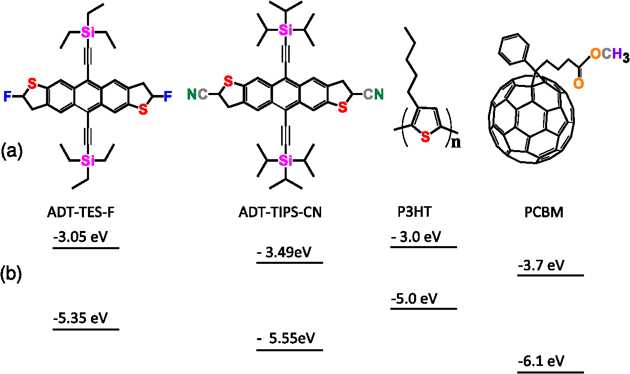
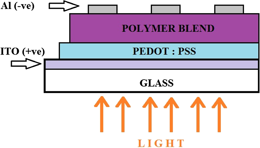
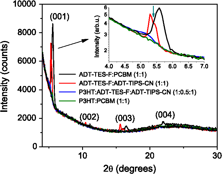
1.IntroductionOrganic solar cells have been a subject of intensive research.1–3 Over the past 10 years, an impressive increase in power conversion efficiency (PCE) has been achieved due to an improved understanding of the physics behind charge carrier photogeneration and transport in organic semiconductors, as well as of useful structure-property relationships.2–6 PCEs of 10% to 12% have been demonstrated in several organic donor-acceptor (D/A) systems.1 Currently, most successful organic solar cells utilize polymer:fullerene bulk heterojunctions (BHJs)4 or vacuum-deposited small-molecule (SM)-based multilayer films.7 Solution-processable SMBHJs, as well as polymer-based BHJs with nonfullerene acceptors, are still lacking in performance,8–11 although considerable progress has been made in these systems as well.12,13 For example, the best SMBHJs currently exhibit PCEs of ,14 and PCEs of 10.1% have been demonstrated in solution-deposited tandem SM cells.15 However, the quest for molecules which would yield more efficient SMBHJs remains open. Another promising direction which may lead to considerable improvements in solution-processable solar cell PCEs is organic ternary BHJs, in which an additional donor (D) or acceptor (A) molecule is introduced into the standard, binary blends of donor and acceptor, thus creating or blends.16 Such additions may allow tuning of open-circuit voltage ()17 and can enable a variety of processes that may be beneficial for the PCE. These include Förster resonant energy transfer (FRET), cascade charge transfer (CT),18 and parallel-like CT.16 For example, up to a 38% PCE enhancement was observed in P3HT:PCBM blends upon addition of wt% of a squaraine dye due to FRET that extended the spectral sensitivity of the cell to near-infrared (IR) wavelengths.19 Also, increased short-circuit currents () due to additional charge transport pathways and enhanced charge photogeneration enabled by additives to the binary D:A blends were reported in a variety of BHJs.19 However, development of efficient ternary blends is a relatively new area, and routes of optimizing such blends to achieve high PCEs are not well understood. In this paper, we explore solution-processable ternary blends and SMBHJs. In particular, we investigate the following systems: (1) polymer donor (D):fullerene acceptor (): SM nonfullerene acceptor (), (2) polymer donor ():SM donor ():SM nonfullerene acceptor (A), and (3) SM donor:SM nonfullerene or fullerene acceptor. In blends (1) and (2), we seek to establish the effects of CT state formation and its properties, as well as of cascade CT and/or parallel-like CT, on various solar cell characteristics. Our particular focus is on the relationship between photophysical processes mediated by the additional donor or acceptor molecules and solar cell characteristics. Systems (3) utilize the same SMs as those used in systems (1) and (2), thus providing additional insight into the relationship between D/A interactions and solar cell performance. Since our main focus is on the photophysical picture and on correlations between particular photoinduced interactions and device characteristics, no optimization of device geometry or blend composition and processing conditions to achieve the highest PCEs was performed for any of the blends studied. 2.Experiments2.1.Materials ConsiderationsMaterials used in our studies and their HOMO and LUMO energies (obtained from the manufacturer or differential pulse voltammetry)20,21 are shown in Fig. 1. Regioregular, electronic grade poly[3-hexylthiophene-2,5-diyl] (P3HT) and [6,6] phenyl C61 butyric acid methyl ester (PCBM) were obtained from Sigma Aldrich and Nano-C, respectively, and were used as received. Synthesis and optical and (photo)conductive properties of functionalized anthradithiophene (ADT) derivatives, ADT-TES-F and ADT-TIPS-CN in Fig. 1, were reported elsewhere.20,22 The choice of these ADT derivatives for the present study of ternary blends was guided by the following considerations. Based on the HOMO and LUMO energies of Fig. 1, addition of ADT-TIPS-CN to the P3HT (D):PCBM () blend introduces the possibility of cascading CT. By contrast, the energies of ADT-TES-F are similar to those of P3HT, so ADT-TES-F would be expected to act as an additional donor () for any ternary blend with P3HT as the main donor, thus enabling parallel-like CT. Furthermore, our previous work revealed that in films containing ADT-TES-F donor and ADT-TIPS-CN acceptor molecules, either efficient FRET from ADT-TES-F to ADT-TIPS-CN occurred or a highly emissive CT state (exciplex) formed, depending on the distance between the D and A molecules.23 This prompted us to explore P3HT ():ADT-TES-F ():ADT-TIPS-CN (A) ternary blends and, in particular, to investigate the possible effects of FRET and/or exciplex formation on the solar cell characteristics. Finally, we have previously done extensive experimental and computational work aimed to understand time-resolved charge carrier and exciton dynamics in films of pristine ADT-TES-F and its blends with a variety of SM acceptors (including ADT-TIPS-CN and PCBM) using planar interdigitated photodetector-type geometry.20,21,23–28 In the present study, we sought to apply insights from our previous work to understanding the performance of these derivatives in solar cells. 2.2.Fabrication and Characterization of Solar CellsDevices were fabricated on cleaned polished float indium tin oxide (ITO, )-coated glass. A thin layer () of poly(3,4-ethylenedioxythiophene)-poly(styrenesulfonate) (PEDOT:PSS) was spun onto ITO substrates at 6000 rpm and dried on a hotplate at 130°C for 5 min. Stock solutions of donor and acceptor molecules, as well as additives, were prepared in chlorobenzene at concentrations of . Then, solutions of donor, acceptor and additives were mixed at appropriate concentrations to achieve the weight ratio of and sonicated for 1 h. Next, a composite layer was deposited by spin casting the mixture at 1000 rpm and was kept at 100°C for 10 min. No high-temperature annealing was performed. Finally, an aluminum (Al) back electrode was deposited by thermal evaporation at , using a Veeco 7700 evaporator. Several devices were made on each substrate with their area () defined using a shadow mask. The cross-sectional structure and bias configurations of the devices are schematically shown in Fig. 2. Current-voltage (I-V) measurements were carried out using a Keithley 237 source-measure unit. For photo I-V measurements, devices were illuminated at using a solar simulator (Oriel 96000) with an AM 1.5G filter. 2.3.Film Structure CharacterizationThe structure of resulting BHJ films was assessed in devices by in situ measurements of x-ray diffraction (XRD) using the Bruker D8 XRD system. Figure 3 shows XRD results for out-of-plane structures in ADT-TES-F:PCBM (), and ADT-TES-F:ADT-TIPS-CN (), and P3HT:PCBM () binary blends and in the P3HT:ADT-TES-F:ADT-TIPS-CN () ternary blend. At room temperature, single ADT-TES-F (ADT-TIPS-CN) crystals have a triclinic structure with unit cell parameters (8.67 Å), (10.28 Å), (12.63 Å), (95.52°), (104.36°), (102.48°).29,30 Solution-deposited pristine ADT-TES-F films exhibit XRD peaks at 5.4, 16.3, and 21.7 deg corresponding to the () (, 3, 4) orientations, which indicate a crystalline structure with a vertical spacing of 16.6 Å (d-spacing).25,31 The (001) crystal orientation, predominant in ADT-TES-F films, corresponds to the molecular -planes and the long axis of the conjugated core oriented approximately in the plane of the film, which enables efficient charge transport in ADT-TES-F thin-film-transistors (TFTs).31,32 The binary blends of ADT-TES-F with PCBM or with ADT-TIPS-CN acceptors (Fig. 3) preserved the tendency of ADT-TES-F to form crystallites with () orientations and exhibited co-existence of structures matching those in the pristine ADT-TES-F films and those with the d-spacing slightly modified by the acceptor. In particular, in the ADT-TES-F blend with PCBM (ADT-TIPS-CN), the modified structure was characterized by a d-spacing of (), which is slightly lower (higher) than that in pristine ADT-TES-F films. No crystalline domains of PCBM or ADT-TIPS-CN were detected in any binary or ternary blends studied. Likewise, no crystalline order of P3HT was observed in the P3HT:PCBM () blend, in agreement with previous studies of such blends prepared using similar conditions,33 or in the P3HT:PCBM-based ternary blends. The P3HT:ADT-TIPS-CN () binary and P3HT:ADT-TES-F:ADT-TIPS-CN () ternary blends exhibited a weak feature between 4.8 and 5.3 deg (inset of Fig. 3), which did not change with the ADT-TES-F concentration. This suggests the presence of a small number of ordered P3HT domains with a d-spacing of , which would be consistent with the (100) orientation of P3HT crystallites.34 No crystalline domains of ADT-TES-F were detected in the P3HT:ADT-TES-F:ADT-TIPS-CN () ternary blends in the studied range of . 2.4.Measurements of Optical and Photoluminescent PropertiesOptical absorption was measured with an Ocean Optics USB-2000 spectrometer using an Ocean Optics LS-1 tungsten halogen lamp as the light source. Photoluminescence (PL) was measured with an Ocean Optics USB-2000FLG spectrometer using a 532 nm continuous wave (cw) Coherent Verdi-5 laser for excitation.24,25 PL spectra were converted to energy units and fit with multiple Gaussian functions as described in our previous paper26 to extract peak positions and widths. PL lifetime measurements were performed via a time-correlated single-photon counting method (PicoQuant TimeHarp 200) using a single-photon avalanche photodiode (Molecular Photonic Devices) for detection. The excitation source was a pulsed 532 nm laser with a fluence of from Altechna (STA-01-SH-4-MOPA, 470 ps, 50 kHz, Q-switched frequency doubled Nd:YAG). In all PL measurements, a Semrock 532 nm RazorEdge long-pass filter was used to remove the laser line. To measure the PL lifetimes of specific emission bands, Chroma E625SP and HQ680LP and Thorlabs RG850 filters were used. The data were fit with a single exponential function [, where is the PL lifetime]. The instrument response function (IRF) () was recorded using scattered light from a frosted glass slide. Most PL measurements were carried out in the same devices as those used in measurements of solar cell characteristics. Additionally, optical absorption and PL properties of control samples ADT-TES-F:PMMA () and ADT-TIPS-CN:PMMA () (PMMA = poly(methyl)methacrylate) were investigated to help in distinguishing between various types of intermolecular interactions in solar cells containing ADT-TES-F and/or ADT-TIPS-CN molecules. Here, PMMA was chosen as a neutral spacer between ADT molecules, having shown no interaction with ADT derivatives in our previous studies.23,27 For PL imaging, the samples were placed under an Olympus IX-71 microscope and excited with a 532-nm cw laser through a objective in the wide-field geometry. Images were obtained using a combination of a 540LP dichroic, 537LP and 695SP or 720LP emission filters (all from Chroma Tech.) and an Andor iXon DU897 EMCCD camera. 3.Results and Discussion3.1.Optical and PL Properties: Intermolecular Interactions in Binary BlendsFirst, we investigated simpler, binary blends in order to identify intermolecular interactions in all intended components for our ternary blends and SMBHJs. Figure 4 shows optical absorption and PL spectra of ADT-TES-F:PMMA (), ADT-TIPS-CN:PMMA (), and ADT-TES-F:ADT-TIPS-CN () films. In ADT-TES-F:PMMA () films, spectra characterized by a lowest-energy absorption peak at (2.27 eV) and highest-energy PL emission at (2.1 eV) were similar to those in pristine ADT-TES-F films, previously attributed to disordered H-aggregates [Figs. 4(a) and 4(b)].26,27 The PL lifetime of ADT-TES-F aggregates in ADT-TES-F:PMMA () films was 1.9 ns [Fig. 4(c)], in agreement with previous studies.26,35 Optical absorption of ADT-TIPS-CN:PMMA () films was red-shifted as compared to ADT-TES-F:PMMA films, with the lowest-energy peak at (2.09 eV).35 PL spectra of ADT-TIPS-CN:PMMA films [Fig. 4(b)] had contributions consistent with those of ADT-TIPS-CN aggregates20 characterized by PL emission peaked at (2.08 eV) with a lifetime of and an excimer emission peaked at (1.72 eV) with a lifetime of 2.9 ns [Fig. 4(c)]. Fig. 4Normalized optical absorption (a), photoluminescence (PL) spectra (b), and PL lifetime decays (c) of ADT-TES-F:PMMA (), ADT-TIPS-CN:PMMA (), and ADT-TES-F:ADT-TIPS-CN () films. The IRF and exponential fits are also included in (c). 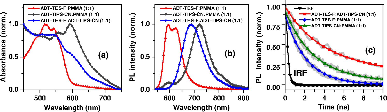 Optical absorption of ADT-TES-F:ADT-TIPS-CN () films was a superposition of the ADT-TES-F and ADT-TIPS-CN absorption spectra [Fig. 4(a)], whereas the PL emission was dominated by that from the ADT-TES-F/ADT-TIPS-CN exciplex peaked at (1.80 eV) [Fig. 4(b)], with a lifetime of 4.4 ns [Fig. 4(c)]. CT state formation and its properties in various D:A blends with the ADT-TES-F donor have been previously reported.21,23,24 Emissive CT states (exciplexes) were observed when the difference in LUMO energies between the donor and acceptor () was , which is the case for the ADT-TIPS-CN acceptor. An exciplex with a lifetime of and energy of 1.86 eV, exactly matching the energy difference between the HOMO of the ADT-TES-F donor [] and the LUMO of the ADT-TIPS-CN acceptor [], was observed in ADT-TES-F:ADT-TIPS-CN blends with much higher concentrations of the donor than of the acceptor, such as ADT-TES-F:ADT-TIPS-CN () or ().21,23,36 A 0.06 eV down-shift in the exciplex energy (Table 1) and its considerably shorter lifetime in the ADT-TES-F:ADT-TIPS-CN () blend, as compared to asymmetric ADT-TES-F donor-dominated blends, suggests a modified morphology of the D/A interface in the symmetric blends, which promotes energy relaxation and nonradiative recombination of CT states in these SMBHJs. Table 1Electrochemical, photophysical, and solar cell parameters of selected bulk heterojunctions (BHJs).
aThe lower optical gap energy between the D or A in binary blends or the lowest of three molecules in ternary blends. Optical absorption and PL spectra of pristine P3HT, P3HT:ADT-TIPS-CN (), and P3HT:ADT-TES-F () films are shown in Figs. 5(a) and 5(b). No significant spectral broadening to achieve photoresponse at longer wavelengths than that with pristine P3HT was observed in either blend. No low-energy CT states formed between P3HT and ADT molecules were apparent in the absorption spectra. The PL spectra of P3HT:ADT-TIPS-CN () films were dominated by ADT-TIPS-CN emission at to 700 nm (exhibiting a vibrational mode progression with peaks, where , 1, 2),26 while the P3HT emission was effectively quenched. No ADT-TIPS-CN excimer emission, dominant in ADT-TIPS-CN:PMMA () films (Fig. 4(b)), was observed, which suggests that photoinduced interactions between P3HT and ADT-TIPS-CN molecules dominated those between adjacent ADT-TIPS-CN molecules, thus preventing excimer formation. Indeed, a PL band in the 800 to 950 nm region with a dominant peak (1.4 eV) was observed. Such near-IR emission was not present either in P3HT pristine films or in ADT-TIPS-CN:PMMA films. To further investigate the origin of this near-IR emission, we separately measured PL lifetimes for the emission at wavelengths and [Fig. 5(c)]. The lifetimes yielded 0.34 and 0.69 ns, respectively, which indicate that these emissions originate from different species. Therefore, we assign the 1.4 eV transition, which is 0.11 eV below (Table 1), to an emissive CT state (exciplex) formed between P3HT and ADT-TIPS-CN. Fig. 5Normalized optical absorption (a) and PL (b) of pristine P3HT, P3HT:ADT-TES-F (), and P3HT:ADT-TIPS-CN () films. (c) PL lifetime decays of P3HT:ADT-TES-F (), P3HT:ADT-TIPS-CN () (590–620 nm and 800–950 nm bands separately), and ADT-TES-F:ADT-TIPS-CN (). The IRF and exponential fits are also included in (c). 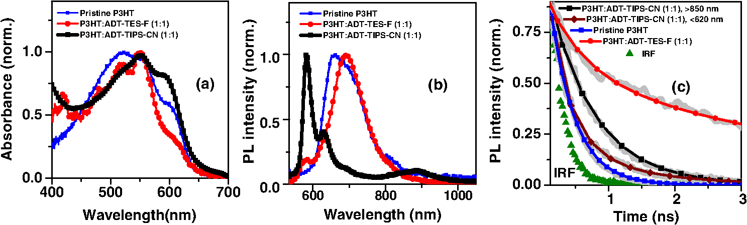 In P3HT:ADT-TES-F () blends, the PL emission was dominated by a transition at (1.79 eV), with a small residual contribution from the ADT-TES-F aggregate emission peaked at [Fig. 5(b)]. The dominant band had a PL lifetime of 3.1 ns [Fig. 5(c)], longer than that of P3HT ()38 or of ADT-TES-F aggregates (1.9 ns). Therefore, we tentatively assign the 1.79 eV emission, which is 0.16 eV below (Table 1), to a P3HT/ADT-TES-F exciplex. 3.2.Solar Cell Performance and Photophysics3.2.1.Ternary blendsversus and —P3HT:PCBM:ADT-TIPS-CN () versus P3HT:PCBM () and P3HT:ADT-TIPS-CN ()In these experiments, we added ADT-TIPS-CN (Fig. 1) at 0 to 5 wt% concentrations (i.e., to 0.105) to the P3HT:PCBM () mixture to create a system and investigate the effects of possible cascading CT (inset of Fig. 6) and other processes on the solar cell characteristics. Figure 6 shows the changes in J-V characteristics upon addition of ADT-TIPS-CN. At our range of ADT-TIPS-CN concentrations, the decreased from 0.6 to 0.52 V, while the fill factor (FF) increased from 0.49 to 0.54 [Fig. 7(a)] as the concentration of ADT-TIPS-CN increased. The decreased by a factor of , which led to a similar reduction in the PCE [Fig. 7(b)]. Therefore, a system with beneficial cascading CT was not realized in these blends. When the PCBM acceptor was completely replaced with ADT-TIPS-CN, which yielded the binary P3HT:ADT-TIPS-CN () blend, the FF was considerably lower, and the was a factor of lower than that in P3HT:PCBM () blends, leading to a considerably lower PCE (Table 2). However, the in the binary P3HT:ADT-TIPS-CN () blend was 0.8 V, which is higher than that in P3HT:PCBM () blends. Fig. 6J-V curves obtained in ternary P3HT:PCBM:ADT-TIPS-CN () solar cells at various concentrations of ADT-TIPS-CN in the 0 to 5 wt% range ( to 0.1). Dark current in the binary blend () is also included. Inset shows HOMO and LUMO energies of molecules. 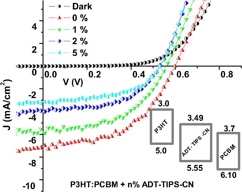 Fig. 7(a) (left axis) and FF (right axis) and (b) (left axis) and PCE (right axis) obtained in ternary P3HT:PCBM:ADT-TIPS-CN () blends as a function of ADT-TIPS-CN concentration in the 0 to 5 wt% range ( to 0.1). Each value represents an average over four devices, and error bars reflect spread in values. 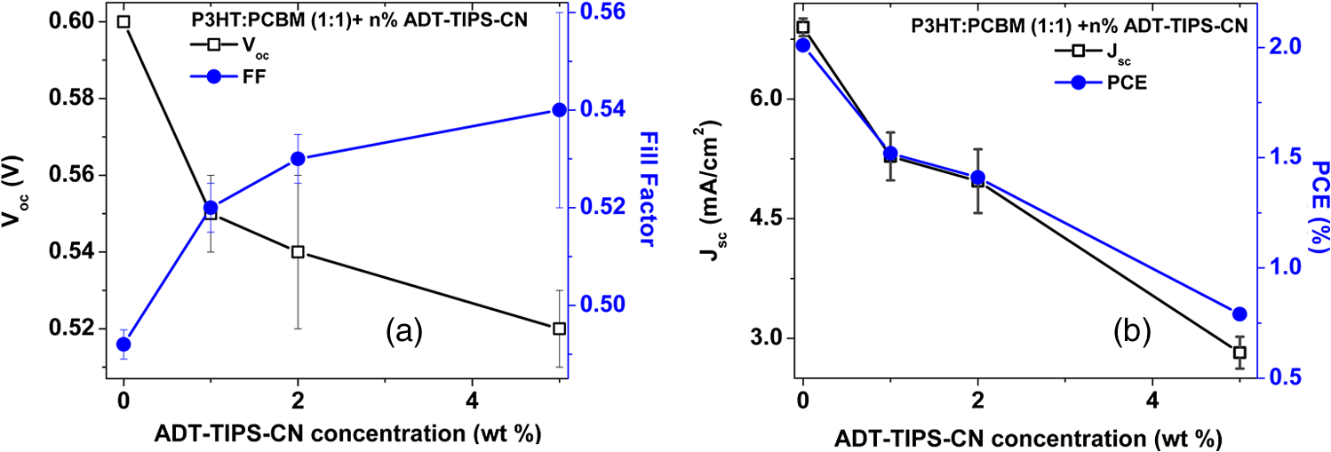 Table 2Solar cell characteristics of selected devices.
In order to gain insights into the observed trends, we considered the optical and PL properties of these films. Addition of ADT-TIPS-CN to P3HT:PCBM at low concentrations did not significantly change the optical absorption of P3HT:PCBM films; the absorption spectra of all films were dominated by that of P3HT shown in Fig. 5(a). The PL spectra were a superposition of the P3HT and ADT-TIPS-CN bands shown in Fig. 5(b), and the contribution of ADT-TIPS-CN emission to the overall PL spectrum of the ternary blend increased as the ADT-TIPS-CN concentration increased. No evidence of P3HT and ADT-TIPS-CN interaction, such as exciplex formation, was observed at 0 to 5 wt% concentrations of ADT-TIPS-CN. Given the HOMO and LUMO energies of all constituents of the ternary blend (inset of Fig. 6) and no evidence of low-energy CT states under these conditions,39 the observed decrease in in Fig. 7(a) is unexpected. However, it is possible that the addition of ADT-TIPS-CN increased the density of defects that act as charge traps, which has been known to negatively impact .40 Such trap states would also increase charge carrier recombination resulting in a lower , as observed in Fig. 7(b). No negative effect of such increased recombination on the FF was observed [Fig. 7(a)],41 which would be consistent with a larger contribution of monomolecular trap-assisted recombination (first-order process) than bimolecular recombination (second-order process) into carrier dynamics in the ternary blends as compared to binary P3HT:PCBM blends.18 Binary P3HT:ADT-TIPS-CN () blends showed considerably lower values than those in ternary blends, which suggest low charge photogeneration efficiency. Performance of 22 P3HT-based binary BHJs with various acceptors has been summarized in Ref. 42, and it was concluded that a of at least 0.2 eV was necessary to achieve photoresponse. In our case, a of 0.49 eV was not sufficient to promote efficient charge separation at the D/A interface, which indicates that is not a reliable indicator of photoinduced charge separation.43 Instead, exciplex formation was observed [Fig. 5(b) and Table 1], which most likely favors radiative recombination over dissociation into mobile charge carriers, as has been the case in a variety of D:A blends.21,23–25,28 This depletes more efficient charge photogeneration pathways, thus lowering the . The low-energy exciplex, however, did not seem to negatively impact the .39 versus —P3HT:ADT-TES-F:ADT-TIPS-CN () versus P3HT:ADT-TIPS-CN ()In these experiments, we added ADT-TES-F (Fig. 1) at 0 to 20 wt% concentrations (i.e., to 0.5) to the P3HT:ADT-TIPS-CN () blend to realize a system, in which ADT-TES-F would act as an additional donor (). As discussed in Sec. 2.3, the ADT-TES-F derivative cast from solution onto glass substrates forms polycrystalline films with the crystallites predominantly oriented such that their plane is in the plane of the substrate [(001) orientation].25,31,32 Such structural arrangement results in strong overlap in the -stacking directions of ADT-TES-F, which explains the good performance of spin-cast ADT-TES-F TFTs, characterized by hole mobilities of .31,32 Charge transport in the direction of the crystal -axis, which is important for the vertical device geometry of a solar cell, is not expected to be efficient. However, in the ternary blends under study, no ADT-TES-F crystallites were detected by the XRD (Fig. 3), and it is possible that some fraction of ADT-TES-F molecules could form amorphous aggregates27 favorable for efficient vertical charge transport. Additionally, pristine ADT-TES-F films exhibit fast charge carrier photogeneration and high photoconductive gains,20 which could improve the overall charge photogeneration efficiency in the ternary blends. Finally, in ternary blends, ADT-TES-F and ADT-TIPS-CN molecules may form a FRET pair, as has been observed in ADT-TES-F:ADT-TIPS-CN:PMMA blends,23 which could also affect charge carrier photogeneration. Figure 8 shows the effects of ADT-TES-F addition to the binary P3HT:ADT-TIPS-CN () blend. The of observed in the P3HT/ADT-TIPS-CN blend slightly decreased, most likely due to an increase in charge trap density,40 and remained between and 0.75 V for ADT-TES-F concentrations of up to 10 wt%. The FF slightly increased, similar to observations in the P3HT:PCBM:ADT-TIPS-CN ternary blends. As the ADT-TES-F concentration further increased, a drop in was observed, yielding 0.54 V at 20 wt% [Fig. 8(a)]. When the ADT-TIPS-CN was completely replaced with ADT-TES-F, in the binary P3HT:ADT-TES-F () blend, the decreased to 0.46 V (Table 1). As expected, the improved upon ADT-TES-F addition in the range of 1 to 20 wt%, by a factor of to 3, leading to an improvement in the PCE by a factor of to 4 in the ternary blends, depending on the ADT-TES-F concentration, as compared to the binary P3HT:ADT-TIPS-CN () blend [Fig. 8(b)]. However, when ADT-TIPS-CN was completely replaced by ADT-TES-F, yielding the binary P3HT:ADT-TES-F () blend, the and PCE were similar to those in the binary P3HT:ADT-TIPS-CN () blend. Moreover, a considerably lower in the P3HT:ADT-TES-F () blend was observed as compared to that in P3HT:ADT-TIPS-CN () (Table 2), a result that cannot be rationalized based on the HOMO and LUMO energies of molecules (Fig. 1). Fig. 8(a) (left axis) and FF (right axis) and (b) (left axis) and PCE (right axis) obtained in ternary P3HT:ADT-TES-F:ADT-TIPS-CN () blends as a function of ADT-TES-F concentration in the 0 to 20 wt% range ( to 0.5). Each value represents an average over four devices, and error bars reflect spread in values. 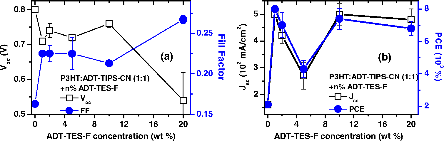 Next, we sought to relate the above results to photophysics in these films. PL spectra of selected ternary samples are shown in Fig. 9(a). At ADT-TES-F concentrations below 20 wt%, the PL spectra were similar to those of P3HT:ADT-TIPS-CN (), with varying relative contributions of the 580 to 700 nm and 800 to 950 nm bands. The former band is a combination of ADT-TIPS-CN and ADT-TES-F aggregate emission [Fig. 4(b)] and of a residual P3HT emission, whereas the latter band is due to the P3HT/ADT-TIPS-CN exciplex [Fig. 5(b)]. The relative contributions of these two bands to the PL spectra did not exhibit any particular trends with the ADT-TES-F concentration, and so these variations were most likely due to differences in film morphology, as illustrated below. FRET between ADT-TES-F and ADT-TIPS-CN, which should take place in the ternary blends at sufficiently low ADT-TES-F concentrations,23 could not be confirmed due to the complexity of PL emission in the ternary blends. However, it is possible that a part of the observed improvement in in the ternary P3HT:ADT-TES-F:ADT-TIPS-CN blends, as compared to the binary P3HT:ADT-TIPS-CN blends, is mediated by FRET. No CT states formed between P3HT and ADT-TES-F or between ADT-TES-F and ADT-TIPS-CN were apparent at ADT-TES-F concentrations wt%. In P3HT:ADT-TES-F:ADT-TIPS-CN blends with 20 wt% of ADT-TES-F, the PL emission was dominated by that from the ADT-TES-F/ADT-TIPS-CN exciplex with the energy of 1.86 eV, exactly matching [Fig. 9(a) and Table 1].23,26 Although observation of ADT-TES-F/ADT-TIPS-CN exciplex formation coincided with a dramatic decrease in in the ternary blends [Fig. 8(a)], these observations are most likely not directly related. Instead, they indicate that a sufficiently high concentration of ADT-TES-F in the ternary blend, such that ADT-TES-F/ADT-TIPS-CN exciplex formation is readily observed, is also high enough to tune the closer to that in the binary P3HT:ADT-TES-F () blend (Table 2). Fig. 9(a) PL spectra of ternary P3HT:ADT-TES-F:ADT-TIPS-CN blends with various ADT-TES-F concentrations. Spectrum of a binary P3HT:ADT-TES-F blend is also included for reference. (b)–(g): PL images of P3HT:ADT-TES-F:ADT-TIPS-CN () films with 2 wt% [(b) and (e)], 5 wt% [(c) and (f)], and 20 wt% [(d) and (g)] of ADT-TES-F. Images in (b)–(d) and in (e)–(g) correspond to PL emission from the same film areas at (dominated by ADT-TES-F and ADT-TIPS-CN) and at (dominated by the P3HT/ADT-TIPS-CN exciplex), respectively. 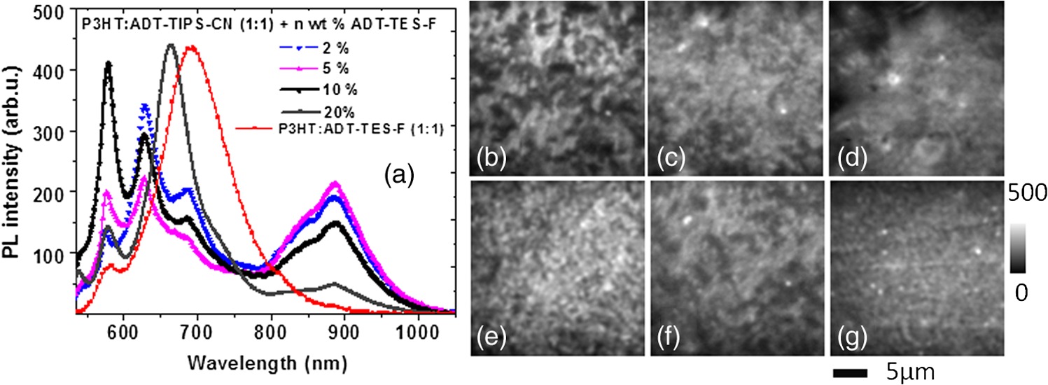 In order to gain further insight into the variation in across ADT-TES-F concentrations in the ternary blends [Fig. 8(b)], we performed spectral region-selective PL imaging of P3HT:ADT-TES-F:ADT-TIPS-CN ternary blends containing various ADT-TES-F concentrations. Figures 9(b) to 9(g) show PL images of films with ADT-TES-F concentrations of 2 wt% [(b) and (e)], 5 wt% [(c) and (f)], and 20 wt% [(d) and (g)] obtained from the same film areas at emission wavelengths of [(b)-(d)] and [(e)-(g)]. In particular, emission at is dominated by that from ADT-TIPS-CN and ADT-TES-F, whereas that at is mostly due to the P3HT/ADT-TIPS-CN exciplex (Sec. 3.1). Therefore, images in Figs. 9(e) to 9(g) reflect the morphology of the interface between P3HT and ADT-TIPS-CN depending on the film. For example, the film with 2 wt% of ADT-TES-F exhibited ADT-TES-F- and ADT-TIPS-CN-rich (bright) and P3HT-rich (dark) regions [Fig. 9(b)] and extensive networks of P3HT:ADT-TIPS-CN interfaces surrounding sub-micron-size domains of P3HT, ADT-TIPS-CN, and ADT-TES-F molecules not interacting with each other [Fig. 9(e)]. In the film with 5 wt% of ADT-TES-F, lower PL image contrast was observed [Fig. 9(c)], which suggests more efficient mixing of various components of the ternary blend, resulting in large areas of intermixed P3HT and ADT-TIPS-CN molecules accompanied by large areas of “noninteracting” molecules [Fig. 9(f)]. The PL image of the film with 20 wt% of ADT-TES-F, in which the PL spectrum at was dominated by the ADT-TES-F/ADT-TIPS-CN exciplex [Fig. 9(a)], was consistent with efficient mixing between ADT-TES-F and ADT-TIPS-CN molecules [Fig. 9(d)]. However, networks of P3HT/ADT-TIPS-CN interfaces could still be observed [Fig. 9(g)], similar to those in the film with 2 wt% of ADT-TES-F in Fig. 9(e). Comparison between the solar cell characteristics of Fig. 8 and the PL data of Fig. 9 suggests that devices with the lowest [P3HT:ADT-TES-F:ADT-TIPS-CN (), i.e., with 5 wt% ADT-TES-F in Fig. 8(b)] had the highest contribution of the P3HT/ADT-TIPS-CN exciplex into the overall PL spectrum of the film, enabled by efficient intermixing of P3HT and ADT-TIPS-CN in these films [Figs. 9(a) and 9(f), respectively]. Such morphology is not conducive for efficient photoinduced charge separation, in agreement with previous studies.24,25 As discussed in Sec. 3.1, the PL emission of the binary P3HT:ADT-TES-F () blend was dominated by the P3HT/ADT-TES-F exciplex [Fig. 5(b) and Table 1]. Since the was low in this blend, it follows that the P3HT/ADT-TES-F exciplex was inefficient in generating mobile charge carriers. Note that in spite of a very low of 0.05 eV in the P3HT:ADT-TES-F blend, the was comparable to that in the P3HT:ADT-TIPS-CN blend with a of 0.49 eV, supporting our previous statement that cannot predict the efficiency of photoinduced charge separation.37,43,44 A considerably higher was expected from the binary P3HT:ADT-TES-F blend as compared to that in the P3HT:ADT-TIPS-CN blend, based on the LUMO energies of the ADT-TES-F and ADT-TIPS-CN (Fig. 1), but this was not observed (Table 1). Since the exciplex-forming properties of these two derivatives with P3HT were similar (Table 1), recombination of exciplex states39 could not account for the observed differences. Therefore, in order to gain further insight into these observations, we removed the P3HT and explored binary SMBHJ solar cells with ADT-TES-F as the only donor. 3.2.2.Small-molecule D:A systems—ADT-TES-F:PCBM and ADT-TES-F:ADT-TIPS-CNSolar cell characteristics of several D:A blends with ADT-TES-F as the donor are summarized in Table 2. In pristine ADT-TES-F diodes, the of 0.95 V was consistent with the built-in voltage caused by differences in the work functions of Al (4.1 eV) and ITO/PEDOT:PSS (5.1 eV). The of , only slightly lower than in P3HT:ADT-TES-F () and P3HT:ADT-TIPS-CN () blends, was observed (Table 2). This confirms that in the P3HT:ADT-TES-F () blend, most charge carriers are generated in separate P3HT and ADT-TES-F domains rather than at the P3HT/ADT-TES-F interfaces. In ADT-TES-F:ADT-TIPS-CN () and ADT-TES-F:PCBM () blends, the increased by a factor of and of , leading to improvements in PCEs by a factor of and , respectively, as compared to pristine ADT-TES-F films. In the ADT-TES-F:ADT-TIPS-CN () blend, which had a considerably broader absorption spectrum than pristine ADT-TES-F [Fig. 4(a)], a relatively small improvement in the with respect to that in pristine ADT-TES-F films was due to the formation of a highly emissive exciplex [Fig. 4(b)], which has been shown to be detrimental for charge photogeneration efficiency.21,23,26,36 In the ADT-TES-F:PCBM blends, a considerably larger improvement in was observed (Table 2), most likely due to both enhanced charge photogeneration efficiency, previously observed in similar blends,25,28 and improved electron mobility. However, the of in the ADT-TES-F:PCBM () blend was more than an order of magnitude lower than that in the P3HT:PCBM () blend, in part due to the ADT-TES-F:PCBM film structure featuring crystalline ADT-TES-F domains with the orientations not favorable for vertical charge transport (Fig. 3).25 The FF was relatively low in all ADT-TES-F-containing SMBHJs, in part due to the poor quality of interface between the crystalline ADT-TES-F domains and the electrodes. In contrast to , which showed predictable trends upon ADT-TIPS-CN or PCBM acceptor addition to ADT-TES-F, the behavior of was more intriguing. In the ADT-TES-F:ADT-TIPS-CN () blend, the was 0.77 V, similar to 0.8 V in the P3HT:ADT-TIPS-CN () blend. This result is consistent with the relative HOMO and LUMO energies of ADT-TES-F, P3HT, and ADT-TIPS-CN molecules (Fig. 1) and does not seem to be affected by the presence32 of the ADT-TES-F/ADT-TIPS-CN exciplex at 1.8 eV in the ADT-TES-F:ADT-TIPS-CN () blend or the P3HT/ADT-TIPS-CN exciplex at 1.4 eV in the P3HT:ADT-TIPS-CN () blend (Table 1). However, in ADT-TES-F:PCBM () blends, a of 0.15 V was observed (Table 2), considerably lower than the of 0.6 V obtained in P3HT:PCBM blends. To gain further insight into the unexpectedly low in ADT-TES-F:PCBM blends, we compared the time-resolved charge carrier dynamics of ADT-TES-F:PCBM blends with those of pristine ADT-TES-F and ADT-TES-F:ADT-TIPS-CN films, which we have studied in detail in our previous work.20,21,23–26,28,36 In particular, the has been shown to depend on the mechanism and efficiency of nongeminate recombination,45,46 which can be elucidated by analyzing photocurrent dynamics.28 Figure 10 shows normalized time-resolved photocurrents obtained under a pulsed 470 ps, 532 nm excitation of pristine ADT-TES-F and ADT-TES-F:PCBM () films from Ref. 25 and under a pulsed 100 fs, 400 nm excitation of ADT-TES-F:ADT-TIPS-CN () films from Ref. 36. In these measurements, a fast rise of the photocurrent, limited by the laser pulse width () and by the resolution of the detection system (), respectively, was observed, indicative of fast photogeneration of mobile charge carriers. The photocurrent dynamics at times longer than the pulse width incorporate charge carrier loss due to trapping and recombination.28 Numerical simulations of photocurrent dynamics in pristine ADT-TES-F films and in several ADT-TES-F-based blends have identified bimolecular recombination as the dominant process behind the sub-ns charge carrier loss observed via fast photocurrent decay in the ADT-TES-F film and in the ADT-TES-F:PCBM blend in Fig. 10.25 Drastically different photocurrent dynamics observed in ADT-TES-F: PCBM and ADT-TES-F:ADT-TIPS-CN blends are indicative of enhanced and reduced fast bimolecular recombination, respectively, as compared to pristine ADT-TES-F films under the same excitation conditions.25,36 Based on these observations, fast bimolecular recombination in ADT-TES-F:PCBM blends could be one of the reasons behind the loss of in these blends. Note that the presence of the ADT-TES-F/ADT-TIPS-CN exciplex, which is the dominant photoinduced interaction between ADT-TES-F and ADT-TIPS-CN in binary blends,23 is not directly related to reduced charge carrier recombination; however, charge carrier recombination dynamics in BHJs depend considerably on the morphology of the D/A interfaces, which also determines exciplex properties.21 Numerical modeling of transient photocurrents similar to those in Fig. 10 revealed up to a factor of four enhancement in ultrafast charge carrier separation efficiency in ADT-TES-F:PCBM () films as compared to pristine ADT-TES-F films,25 which is in trend with the values in ADT-TES-F:PCBM SMBHJs in Table 2. A factor of decrease in the transient photocurrent amplitude in ADT-TES-F:ADT-TIPS-CN () films as compared to those in pristine ADT-TES-F films was attributed to inefficient charge photogeneration from exciplex states,36 also consistent with the trends in exciplex-forming blends in Table 2. Fig. 10Normalized transient photocurrents obtained in pristine ADT-TES-F films and ADT-TES-F:PCBM and ADT-TES-F:ADT-TIPS-CN blends upon pulsed photoexcitation. 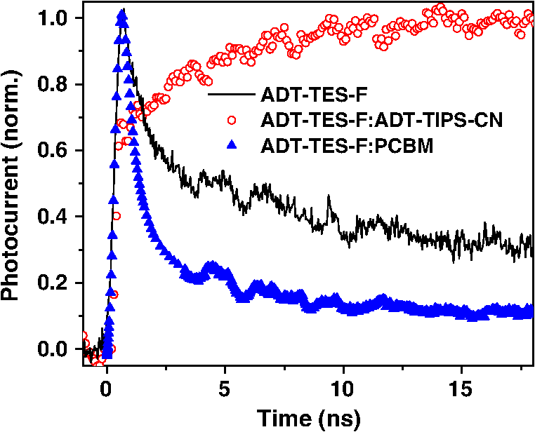 The ADT-TES-F:PCBM () blend exhibited an order of magnitude higher PCE as compared to that in either P3HT:ADT-TIPS-CN () or P3HT:ADT-TES-F () blends, in spite of the considerably lower in the ADT-TES-F:PCBM BHJ (Table 2). Therefore, it appears that when there is a trade-off between achieving high (e.g., due to enhanced recombination) and maximizing (e.g., due to enhanced charge photogeneration efficiency), the latter route is more productive for the PCE.42 4.ConclusionsAddition of a nonfullerene small molecule acceptor ADT-TIPS-CN to “efficient” P3HT:PCBM BHJs led to a reduction in , , and PCE, mostly due to decreased charge photogeneration efficiency and increased disorder. By contrast, addition of the small molecule donor ADT-TES-F to “inefficient” P3HT:ADT-TIPS-CN BHJs led to a factor of 2 to 3 improvement in , which resulted in a factor of 2 to 4 improvement in PCE. In particular, ternary P3HT:ADT-TES-F:ADT-TIPS-CN () blends with to 0.5 exhibited better PCEs than those in the P3HT:ADT-TES-F (), P3HT:ADT-TIPS-CN (), or ADT-TES-F:ADT-TIPS-CN () binary blends. In all blends, exciplex formation did not reduce the , but was correlated with a reduced . Therefore, morphologies leading to efficient intermixing between various components of the blend, which promote exciplex formation, must be avoided. A factor of higher PCE was observed in ADT-TES-F:PCBM () as compared to ADT-TES-F:ADT-TIPS-CN () SMBHJs largely due to enhanced charge carrier photogeneration in the blend with PCBM. In all blends containing the ADT-TES-F derivative, the observed did not show any correlation with expectations based on the HOMO and LUMO energies of Fig. 1. The applicability of HOMO and LUMO energies measured in solution using cyclic or differential pulse voltammetry to solar cell analysis has been questioned in the literature.37,43,44 The importance of including ionization potentials and activation energies of optically excited states43 and of local dielectric environment44 into consideration has been emphasized. While further studies are needed to conclusively establish the dominant loss factor that determines the in our blends, our results clearly highlight the importance of the underlying photophysics, which goes far beyond HOMO/LUMO energy considerations, for solar cell characteristics. AcknowledgmentsThis work was supported by University Grants Commission, India via Indo-US Raman Postdoctoral Fellowship- F.No. 5-50/2013(IC) and the National Science Foundation grant DMR-1207309. J.E.A. and R.H. thank the National Science Foundation (CMMI-1255494) for support of the synthesis of organic semiconductors. ReferencesM. C. ScharberN. S. Sariciftci,
“Efficiency of bulk-heterojunction organic solar cells,”
Prog. Polym. Sci., 38 1929
(2013). http://dx.doi.org/10.1016/j.progpolymsci.2013.05.001 PRPSB8 0079-6700 Google Scholar
J. ServaitesM. A. RatnerT. J. Marks,
“Organic solar cells: a new look at traditional models,”
Energy Environ. Sci., 4 4410
(2011). http://dx.doi.org/10.1039/c1ee01663f 1754-5692 Google Scholar
Handbook of Organic Materials for Optical and (Opto)electronic Devices, 800 Woodhead Publishing, Oxford
(2013). Google Scholar
S. DimitrovJ. R. Durrant,
“Materials design considerations for charge generation in organic solar cells,”
Chem. Mater., 26 616
(2014). http://dx.doi.org/10.1021/cm402403z CMATEX 0897-4756 Google Scholar
S. Gelinaset al.,
“Ultrafast long-range charge separation in organic semiconductor photovoltaic diodes,”
Science, 343 512
(2014). http://dx.doi.org/10.1126/science.1246249 SCIEAS 0036-8075 Google Scholar
E. BittnerC. Silva,
“Noise-induced quantum coherence drives photo-carrier generation dynamics at polymeric semiconductor heterojunctions,”
Nat. Commun., 5 3119
(2014). http://dx.doi.org/10.1038/ncomms4119 NCAOBW 2041-1723 Google Scholar
A. Troisi,
“What makes fullerene acceptors special as electron acceptors in organic solar cells and how to replace them,”
Adv. Mater., 25 1038
(2013). http://dx.doi.org/10.1002/adma.v25.7 ADVMEW 0935-9648 Google Scholar
J. E. Anthony,
“Small-molecule, nonfullerene acceptors for polymer bulk heterojunction organic photovoltaics,”
Chem. Mater., 23 583
–590
(2011). http://dx.doi.org/10.1021/cm1023019 CMATEX 0897-4756 Google Scholar
J. Roncali,
“Molecular bulk heterojunctions: an emerging approach to organic solar cells,”
Acc. Chem. Res., 42 1719
–1730
(2009). http://dx.doi.org/10.1021/ar900041b ACHRE4 0001-4842 Google Scholar
B. WalkerC. KimT. Q. Nguyen,
“Small molecule solution-processed bulk heterojunction solar cells,”
Chem. Mater., 23 470
–482
(2011). http://dx.doi.org/10.1021/cm102189g CMATEX 0897-4756 Google Scholar
Y. LinY. LiX. Zhang,
“Small molecule semiconductors for high-efficiency organic photovoltaics,”
Chem. Soc. Rev., 41 4245
(2012). http://dx.doi.org/10.1039/c2cs15313k CSRVBR 0306-0012 Google Scholar
A. MishraP. Bauerle,
“Small molecule organic semiconductors on the move: promises for future solar energy technology,”
Angew. Chem.-Int. Ed., 51 2020
–2067
(2012). http://dx.doi.org/10.1002/anie.201102326 ACIEF5 1433-7851 Google Scholar
V. Guptaet al.,
“Barium: an efficient cathode layer for bulk heterojunction solar cells,”
Sci. Rep., 3 1965
(2013). http://dx.doi.org/10.1038/srep01965 SRCEC3 2045-2322 Google Scholar
Y. Liuet al.,
“Solution-processed small-molecule solar cells: breaking the 10% power conversion efficiency,”
Sci. Rep., 3 3356
(2013). http://dx.doi.org/10.1038/srep03356 SRCEC3 2045-2322 Google Scholar
T. Ameriet al.,
“Organic ternary solar cells: a review,”
Adv. Mater., 25 4245
(2013). http://dx.doi.org/10.1002/adma.v25.31 ADVMEW 0935-9648 Google Scholar
R. A. Streetet al.,
“Origin of the tunable open-circuit voltage in ternary blend bulk heterojunction organic solar cells,”
J. Am. Chem. Soc., 135 986
(2013). http://dx.doi.org/10.1021/ja3112143 JACSAT 0002-7863 Google Scholar
C. ProctorM. KuikT. Q. Nguyen,
“Charge carrier recombination in organic solar cells,”
Prog. Polym. Sci., 38 1941
(2013). http://dx.doi.org/10.1016/j.progpolymsci.2013.08.008 PRPSB8 0079-6700 Google Scholar
J. Huanget al.,
“Polymer bulk heterojunction solar cells employing FRET,”
Nat. Photonics, 7 479
(2013). http://dx.doi.org/10.1038/nphoton.2013.82 1749-4885 Google Scholar
A. D. Plattet al.,
“Optical, fluorescent, and photoconductive properties of high-performance functionalized pentacene and anthradithiophene derivatives,”
J. Phys. Chem. C, 113 14006
–14014
(2009). http://dx.doi.org/10.1021/jp904021p 1932-7447 Google Scholar
M. J. Kendricket al.,
“Formation of the donor-acceptor charge transfer exciton and its contribution to charge photogeneration and recombination in small-molecule bulk heterojunctions,”
J. Phys. Chem. C, 116 18108
(2012). http://dx.doi.org/10.1021/jp305913s 1932-7447 Google Scholar
S. Subramanianet al.,
“Chromophore fluorination enhances crystallization and stability of soluble anthradithiophene semiconductors,”
J. Am. Chem. Soc., 130 2706
–2707
(2008). http://dx.doi.org/10.1021/ja073235k JACSAT 0002-7863 Google Scholar
W. E. B. Shepherdet al.,
“Energy transfer and exciplex formation and their impact on exciton and charge carrier dynamics in organic films,”
J. Phys. Chem. Lett., 2 362
–366
(2011). http://dx.doi.org/10.1021/jz101698q 1948-7185 Google Scholar
K. Paudelet al.,
“Small-molecule bulk heterojunctions: distinguishing between effects of energy offsets and molecular packing on optoelectronic properties,”
Jo. Phys. Chem. C, 117 24752
(2013). http://dx.doi.org/10.1021/jp4093089 1932-7447 Google Scholar
K. Paudelet al.,
“Enhanced charge photogeneration promoted by crystallinity in small-molecule donor-acceptor bulk heterojunctions,”
Appl. Phys. Lett., 105 043301
(2014). http://dx.doi.org/10.1063/1.4891758 APPLAB 0003-6951 Google Scholar
A. D. Plattet al.,
“Temperature dependence of charge carrier and exciton dynamics in organic thin films,”
Phys. Rev. B, 84 235209
(2011). http://dx.doi.org/10.1103/PhysRevB.84.235209 PRBMDO 0163-1829 Google Scholar
W. E. B. Shepherdet al.,
“Aggregate formation and its effect on (opto)electronic properties of guest-host organic semiconductors,”
Appl. Phys. Lett., 97 163303
(2010). http://dx.doi.org/10.1063/1.3505493 APPLAB 0003-6951 Google Scholar
B. JohnsonM. J. KendrickO. Ostroverkhova,
“Charge carrier dynamics in organic semiconductors and their donor-acceptor composites: numerical modeling of time-resolved photocurrent,”
J. Appl. Phys., 114 094508
(2013). http://dx.doi.org/10.1063/1.4820259 JAPIAU 0021-8979 Google Scholar
O. D. Jurchescuet al.,
“Effects of polymorphism on charge transport in organic semiconductors,”
Phys. Rev. B, 80 085201
(2009). http://dx.doi.org/10.1103/PhysRevB.80.085201 PRBMDO 0163-1829 Google Scholar
O. D. Jurchescuet al.,
“Organic single-crystal field-effect transistors of a soluble anthradithiophene,”
Chem. Mater., 20
(21), 6733
–6737
(2008). http://dx.doi.org/10.1021/cm8021165 CMATEX 0897-4756 Google Scholar
S. K. Parket al.,
“High-mobility spin-cast organic thin film transistors,”
Appl. Phys. Lett., 93 043301
(2008). http://dx.doi.org/10.1063/1.2952769 APPLAB 0003-6951 Google Scholar
D. J. Gundlachet al.,
“Contact-induced crystallinity for high-performance soluble acene-based transistors and circuits,”
Nat. Mater., 7 216
–221
(2008). http://dx.doi.org/10.1038/nmat2122 NMAACR 1476-1122 Google Scholar
A. Pearsonet al.,
“Rationalizing phase transitions with thermal annealing temperatures for P3HT:PCBM organic photovoltaic devices,”
Macromolecules, 45 1499
(2012). http://dx.doi.org/10.1021/ma202063k MAMOBX 0024-9297 Google Scholar
T. Erbet al.,
“Correlation between structural and optical properties of composite polymer/fullerene films for organic solar cells,”
Adv. Funct. Mater., 15 1193
(2005). http://dx.doi.org/10.1002/(ISSN)1616-3028 AFMDC6 1616-3028 Google Scholar
A. D. Plattet al.,
“Photophysical and photoconductive properties of organic semiconductor composites,”
Proc. SPIE, 7413 7413
–7428
(2009). http://dx.doi.org/10.1117/12.826634 PSISDG 0277-786X Google Scholar
J. Dayet al.,
“Organic semiconductor composites: influence of additives on the transient photocurrent,”
Appl. Phys. Lett., 94
(1), 013306
(2009). http://dx.doi.org/10.1063/1.3062850 APPLAB 0003-6951 Google Scholar
D. VeldmanS. C. J. MeskersR. A. J. Janssen,
“The energy of charge-transfer states in electron donor-acceptor blends: insight into the energy losses in organic solar cells,”
Adv. Funct. Mater., 19 1939
(2009). http://dx.doi.org/10.1002/adfm.v19:12 AFMDC6 1616-3028 Google Scholar
S. CookA. FurubeR. Katoh,
“Analysis of the excited states of regioregular polythiophene P3HT,”
Energy Environ. Sci., 1 294
(2008). http://dx.doi.org/10.1039/b805643a 1754-5692 Google Scholar
C. DeibelT. StrobelV. Dyakonov,
“Role of the charge transfer state in organic donor-acceptor solar cells,”
Adv. Mater., 22 4097
–4111
(2010). http://dx.doi.org/10.1002/adma.v22:37 ADVMEW 0935-9648 Google Scholar
T. RipollesA. GuerreroG. Garcia-Belmonte,
“Polymer defect states modulate open-circuit voltage in bulk heterojunction solar cells,”
Appl. Phys. Lett., 103 243306
(2013). http://dx.doi.org/10.1063/1.4841475 APPLAB 0003-6951 Google Scholar
B. QiJ. Wang,
“Fill factor in organic solar cells,”
Phys. Chem. Chem. Phys., 15 8972
(2013). http://dx.doi.org/10.1039/c3cp51383a PPCPFQ 1463-9076 Google Scholar
B. MinnaertM. Burgelman,
“Empirical study of the characteristics of current-state organic bulk heterojunction solar cells,”
Eur. Phys. J. Appl. Phys., 38 111
(2007). http://dx.doi.org/10.1051/epjap:2007062 EPAPFV 1286-0050 Google Scholar
X. Y. Zhu,
“How to draw energy level diagrams in excitonic solar cells,”
J. Phys. Chem. Lett., 5 2283
(2014). http://dx.doi.org/10.1021/jz5008438 1948-7185 Google Scholar
S. Chenet al.,
“Dielectric effect on the photovoltage loss in organic photovoltaic cells,”
Adv. Mater., 26 6125
(2014). http://dx.doi.org/10.1002/adma.v26.35 ADVMEW 0935-9648 Google Scholar
Z. Beileyet al.,
“Morphology-dependent trap formation in high performance polymer bulk heterojunction solar cells,”
Adv. Energy Mater., 1 954
(2011). http://dx.doi.org/10.1002/aenm.v1.5 ADEMBC 1614-6832 Google Scholar
D. Credgingtonet al.,
“Non-geminate recombination as the primary determinant of open-circuit voltage in polythiophene:fullerene blend solar cells: an analysis of the influence of device processing conditions,”
Adv. Funct. Mater., 21 2744
(2011). http://dx.doi.org/10.1002/adfm.201100225 AFMDC6 1616-3028 Google Scholar
|