|
|
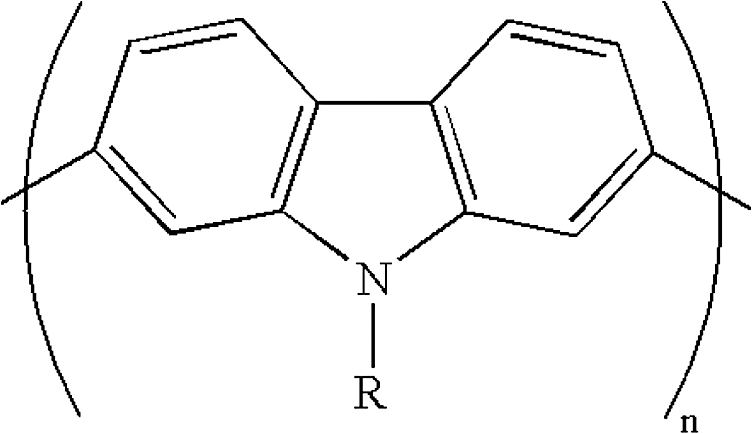
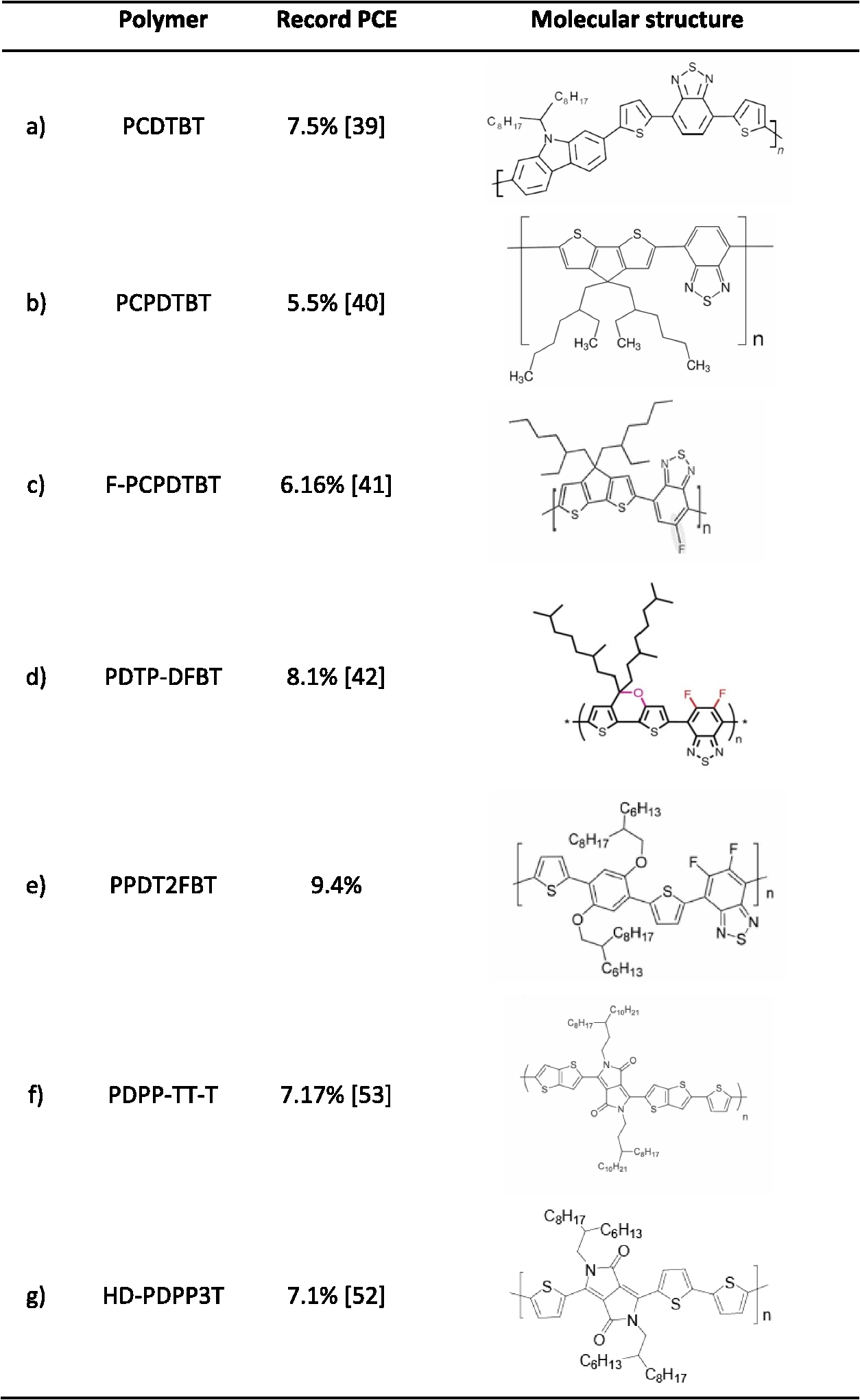
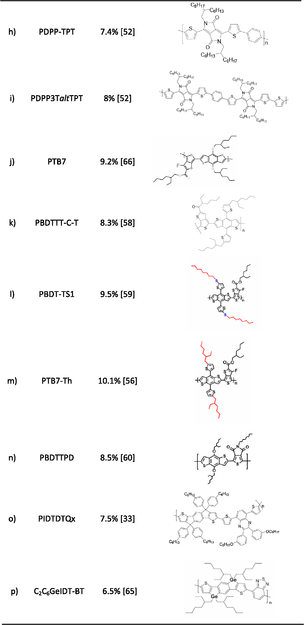
1.IntroductionAn abundance of raw materials, simplicity in device fabrication, and easy integration into different applications, thanks to their lightweight, semitransparency, flexibility, and color tunability, have made organic photovoltaics (OPV) an attractive source of green energy. Nowadays research on this technology is focused on understanding the physics behind the technology and on achieving an efficiency as high as possible. Nelson calculated the limiting efficiency for an ideal single solar cell as a function of the semiconductor bandgap, obtaining a limiting efficiency of at a bandgap of 1.4 eV (885 nm).1 In principle, all the assumptions made for this model are also perfectly valid for organic semiconductors. However, more accurate models explicitly developed for polymer:fullerene bulk heterojunction (BHJ) solar cells and that take into account their detailed working mechanisms predict maximum efficiencies of (Ref. 2) and 21% (Ref. 3) for single and tandem cells, respectively. The main reasons why ideal performances are not achieved are incomplete absorption of the incident light, nonradiative recombination of photogenerated carriers, i.e., excited charges that are trapped at defect sites and recombine before being collected leading to transport losses, and voltage drop due to nonideal series and/or parallel resistance within the bulk and between the active film and the external circuit. All these aspects need to be tackled in order to overcome the current reported record efficiencies and take them closer to the theoretical limits. As we will show, this can be done by actuating on active materials, fabrication/processing procedures (strategies), and device layout/architectures. The efficiency of a solar cell is defined as the ratio between the voltage at open circuit conditions (), the output current at short circuit conditions (), the fill factor (FF) of the device, and the incident light intensity () [see Eq. (1)]. It is clear that maximizing the efficiency is, thus, a matter of increasing , , and FF as much as possible. is ideally limited by the energy difference between the LUMO level of the acceptor and the HOMO level of the donor; therefore, it can be theoretically adjusted up to a certain extent by modifying the energy levels of the materials.4–7 However, is not strictly an active material issue. Suboptimal contacts can lead to either resistive losses—series resistances—and/or current leakage—parallel resistance—that might cause a voltage drop. Therefore, device engineering and cell layout are also important to guarantee a large . This is usually achieved with the use of interlayers, as we will describe in detail in Sec. 4. A high photocurrent () can also be achieved by selecting materials with absorption spectra that overlap the photon flux density and, hence, the incident power spectrum from the Sun. The available power from these cells represents the best compromise between absorption and power delivery. As mentioned above, ideal bandgaps for photovoltaic conversion are in the red and near-infrared part of the electromagnetic spectrum. The so-called low-bandgap (LBG) polymers are synthesized for this purpose.8,9 However, as in the previous case, obtaining a high is not only a matter of the active material. The morphology of the film is crucial in order to ensure efficient charge generation and transport processes.10 Different fabrication/processing procedures can lead to substantially different film morphologies even when the same active materials are used. These will be detailed in Sec. 3. Blends of solvents, the use of additives, manual manipulation of the deposition temperature, and the creation of a solvent saturated atmosphere are some of the strategies most commonly used in order to obtain better control of the film drying process and manipulate the resulting bulk-in morphology.11–18 FF is the most meaningful and sensitive parameter in the characterization of solar cells since it contains information of all the processes involved in charge recombination, transport, and collection. The morphology of the film will, therefore, also have a direct effect on the measured FF. As commented above, deliberate manipulation of the film morphology also results in enhanced FF and device performance. Despite alternative fabrication/processing procedures, a spatial asymmetry that helps create a gradient in charge density can be beneficial to obtain selective charge injection/extraction, reduce leakage current and charge recombination, and improve charge transport. The use of buffer layers has been demonstrated to improve, in this way, contact selectivity and device rectification. Finally, materials with complementary absorption spectra can be stacked together in the same tandem device. This is an alternative device layout/architecture approach in order to maximize the light harvesting and adjust the overall absorption of the cell to the solar irradiance spectrum.19,20 2.MaterialsPolythiophenes are one of the most widely used polymers in the fabrication of organic solar cells due to the good optical and electrical properties and good thermal and chemical stability that they present. Polythiophenes are based on repeating units of thiophenes [see Fig. 1(a)], where different side chains can be added in order to modify the resulting properties.21,22 Poly(3-hexylthiophene) (P3HT) [Fig. 1(b)] has an optical bandgap of 1.9 eV. In the literature, typical efficiency values of to 4% have been achieved by several groups when combined with the fullerene derivative [6,6]-phenyl-C61-butyric acid methyl ester () as electron acceptor.23 However, higher efficiencies close to 4.5% have been reported when samples with higher regioregularity24 and/or [6,6]-phenyl C71-butyric acid methyl ester () instead of are used. P3HT has been, for many years, the standard absorber material used in OPV. In spite of its moderate power conversion efficiency, its acceptable hole mobility, long stability, processability, and scalability make it a potential candidate for the mass-fabrication of modules using roll-to-roll (R2R) compatible deposition techniques.25,26 However, their restricted absorption to limits their efficiency below 5%. Some of the most promising candidates that are being synthesized nowadays to enhance the light harvesting include carbazole-benzothiadiazole copolymers,27,28 diketopyrrolopyrrole (DPP) based copolymers,29,30 benzodithiophene (BDT) derivatives31,32 as well as indacenodithiophene (IDT) based copolymers.33 This new generation of semiconducting copolymers combine electron-rich segments with electron-deficient units, such as DPPs, along the polymer backbone. The selection of different electron-rich comonomers, such as thiophene, fluorine, or carbazole based units among others, determines the optical bandgap, the energy levels, and the carrier mobility of the resulting copolymer. These LBG donor-acceptor polymers present energy gaps in the range of 1.3 to 1.6 eV enabling light absorption in the near-infrared region, which combined with a fullerene derivative are able to extend the absorption of the organic solar cell to the UV/visible as well. In the following, some promising copolymers based on previously mentioned units will be analyzed. 2.1.Polymeric Donors2.1.1.Poly (2,7-carbazoles)The electron-donating nitrogen unit of the central fused pyrrole ring makes carbazoles electron-rich compounds. The solubility of the polymer is ensured by functionalization of the central nitrogen with an alkyl chain (see molecular structure in Fig. 2). Since carbazole derivatives present good thermal and photochemical stability and high charge mobility, they are promising candidates to be incorporated in polymers for photovoltaic applications.22,34,35 The conjugation of the carbazole unit to a benzothiadiazole moiety through a thiophene bridge gives rise to a material known as PCDTBT, see Fig. 3. In combination with as an acceptor, organic solar cells with power conversion efficiencies have been achieved by several groups.36–38 These numbers can be improved to 7.2 to 7.5% by using advanced interface materials and antireflection coatings.27,39 A slightly different approach has been attempted by conjugating the benzothiadiazole moiety to a dithiophene unit instead of a carbazole one. The result is a polymer known as PCPDTBT (Fig. 3). Organic solar cells with efficiencies up to 5.5% are usually reported for this polymer when it is blended with .40 Moreover, by introducing a fluor atom into this molecule (Fig. 3), which lowers the increase of the polymer HOMO level and, thus, the , efficiencies of 6.16% have been also achieved.41 A further modification of this copolymer with two fluor atoms at the benzothiadiazole unit gives rise to a difluorobenzothiadiazole (DFBT) moiety that is further conjugated to a dithienopyran (DTP) segment instead of a single dithiophene. The result is a copolymer known as GPDTP-DFBT (Fig. 3) with efficiencies in single devices of (Ref. 42) and also an outstanding performance in tandem configuration, as we will see in Sec. 4.3. A more developed semicrystalline version known as PPDT2FBT (Fig. 3) forms a well-distributed nanofibrillar networked morphology with the fullerene, which results in balanced hole and electron mobility, and tight interchain packing. Relatively thick films of yield record efficiencies of 9.4%.43 2.1.2.DiketopyrrolopyrrolesSome other promising absorbers for OPV applications are copolymers based on electron-deficient diketopyrrolopyrrole units. The copolymerization of this electron-deficient unit with different electron-rich segments has resulted in solar cells with efficiencies up to 8%.29,44–52 The most promising candidates consist of the conjugation of the DPP moiety to a thienothiophene fragment with a varying number of interconnecting thiophene units. For the simplest case, Meager et al. reported PDPP-TT-T based devices with efficiencies for some particular alkyl chain branching position manipulation (Fig. 3).53 Hendriks et al. also reported efficiencies by conjugating the DPP segment to different oligothiophenes (nT). The best material from this series (DT-PDPP3T, Fig. 3) uses terthiophene as a comonomer and reaches 7.1%. Higher efficiencies of 7.4% have also been achieved by alternating the DPP unit with thiophene-phenylene-thiophene (TPT) segments—PDPP-TPT—(Fig. 3) due to the improvement in the polymerization reaction. Finally, the highest reported efficiency of 8% for a DPP based polymer has been obtained by combining these segments with a terthiophene unit in order to produce a terpolymer called PDPP3TaltTPT (Fig. 3).52 2.1.3.BenzodithiophenesCopolymers based on the alternation of BDT and thieno[3,4-b]thiophene units are also promising absorbers for organic solar cell applications. The thieno[3,4-b]thiophene units stabilize the quinoidal structure of the backbone, thus reducing the energy gap of the polymer to 1.6 eV estimated from the onset of the solid-state absorption (775 nm). The ester substituted thieno[3,4-b]thiophene, instead, makes the polymer soluble and oxidative stable while the rigid backbone ensures a good mobility of holes.54,55 Liang et al. developed several copolymers, known as poly thieno-thiophene benzodithiophenes (PTBs), for which efficiencies up to 7.4% have been achieved by using PTB7 as the absorber (Fig. 3) together with as the electron acceptor for conventional configuration devices. This material is also a good example to illustrate that improving the efficiency of an organic solar cell is not only a matter of the active material. Different processing procedures and cell layouts/architectures, as those being described in this review, have taken the efficiency from 6.22 to 9.2%. Standard PTB7 was later modified by incorporating the 2-(2-ethylhexyl)-thienyl group into the BDT unit of PTB7 to produce PTB7-Th (Fig. 3). Incorporating deterministic aperiodic nanostructures (DANs) based on nanoimprint technology on has resulted in the most efficient single device reported to date with a power conversion efficiency (PCE) of 10.1%.56 Huo et al. also designed and synthesized an interesting thiophene-substituted BDT copolymer with carboxyl-substituted thieno[3,4-b]thiophene, PBDTTT-C-T (Fig. 3), that exhibits good thermal stability and hole mobility. Devices based on PBDTTT-C-T:PCBM processed from orthodichlorobenzene (ODCB) and 3% 1,8-diiodooctane (DIO) resulted in efficiencies of 7.6%.57 This efficiency has been recently pushed up to 8.3% by Adhikary et al. when the cell was exposed to UV-ozone.58 Ye et al. introduced linear alkylthio chains in the BDT-T unit to produce another PBDTTT-based copolymer known as PBDT-TS1 (Table 1) from which record devices of up to 9.48% were obtained.59 Table 1Device photovoltaic parameters of orthodichlorobenzene (ODCB) only, ODCB with 3% 1,8-diiodooctane (DIO), chlorobenzene (CB), and CB with 3% DIO as solvent.55
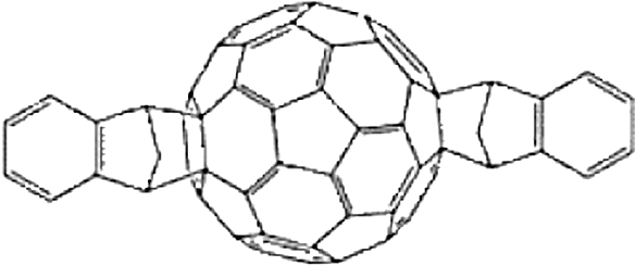
A parallel approach conjugated the BDT fragment to thieno[3,4-c]pyrrole-4,6-dione (TPD) units to result in a copolymer known as PBDTTPD (Fig. 3). Devices based on this polymer in combination with reached PCE values up to 8.5% and values as high as 0.97 V.60 2.1.4.IndacenodithiophenesIDT based copolymers have also resulted in high-efficiency organic solar cells, reporting values .33,61,62 Two cyclopentadiene rings are fused to a benzene in order to form the indaceno unit. This is later joined to a dithiophene fragment to make the IDT moiety, which can then be conjugated to different structures in order to obtain a new family of copolymers. These copolymers generally show high solar flux harvesting, high hole mobility, and deep HOMO energy levels, resulting in devices with values up to 0.9.63,64 Guo et al. developed a copolymer by conjugation of the IDT unit to quinoxaline (Fig. 3), reporting efficiencies for devices based on this copolymer ().33 Similarly, Fei et al. copolymerized the IDT segment to a benzothiadiazole structure. By heteroatom substitution at the cyclopentadiene rings by either silicon or germanium, they also published efficiencies for (Fig. 3) based devices.65 2.2.New Fullerene DerivativesNowadays, almost all reported cells with remarkable efficiencies employ soluble fullerene derivatives as an electron acceptor. Among them, and are the most widely used. Both of them have the same LUMO values, which considerably limit the of operating devices. A new n-type fullerene derivative, indene- bis-adduct (ICBA) (see Fig. 4 for the molecular structure) was demonstrated to be a good alternative acceptor. ICBA has a higher LUMO level () in comparison to either or (), which leads to a higher . In this way, P3HT based devices with ICBA as an acceptor resulted in cells with values of 0.84 V and enhanced PCE of 6.5%.66,67 Cheng et al. also reported P3HT based inverted solar cells using ICBA as an acceptor with a of 0.82 V and a PCE of 4.8%. Further improvement was carried out by the incorporation of a cross-linked fullerene derivative interlayer, C-PCBSD, resulting in the following configuration: ITO/ZnO/C-PCBSD/ICBA:P3HT/PEDOT:PSS/Ag. The incorporation of C-PCBSD increased the photocurrent from 10.6 to and the FF from 55 to 60%, and, thus, pushed up the PCE to 6.2%.68 Many other fullerene derivatives such as bisadducts,5 diphenylmethano fullerenes,69 dimethylphenylmethano fullerene bisadducts,70 and endohedral fullerenes71,72 are also being synthesized and tested in the search for large devices based on internal bulk polymer:fullerene heterojunction systems. In spite of these advances in the synthesis of new fullerenes, and even though soluble derivatives, on average, yield a 10% increase in photocurrent in comparison to ones thanks to a slightly increased absorption in the visible, the lack of a stronger absorption in the visible and in the infrared still hinders further developments in achieving higher conversion efficiencies. Non fullerene containing heterojunction thin films can overcome these shortcomings, since the energy levels (and, hence, absorption) can be modified through the choice of co-couple units due to the well-distributed frontier molecular orbitals.73,74 3.Strategies: Fabrication/Processing ProceduresThe morphology of the film in BHJ solar cells is a critical parameter to control the exciton dissociation rate, optimize charge transport, minimize bulk recombination, maximize the photocurrent, and, hence, enhance the efficiency of the device.75 On one hand, a large number of donor/acceptor interfaces is required in order to dissociate a large number of photogenerated excitons. On the other hand, the domain size of each material phase and the interconnection between them is also important for an efficient charge transport to the corresponding electrodes. Therefore, an optimum balance among the interface area, domain size, and interconnection is required to result in efficient BHJ solar cells.13 This is schematically represented in Fig. 5. Fig. 5Bulk heterojunction devices with different nanomorphologies. (a) Small domains with a large number of interfaces: large charge generation yield but nonefficient charge transport due to recombination. (b) Excessively large domains with a lower interface area between the donor and acceptor: low charge generation yield but good charge transport. (c) Intermediate domain size with an optimized interface area: large charge generation yield and good charge transport. 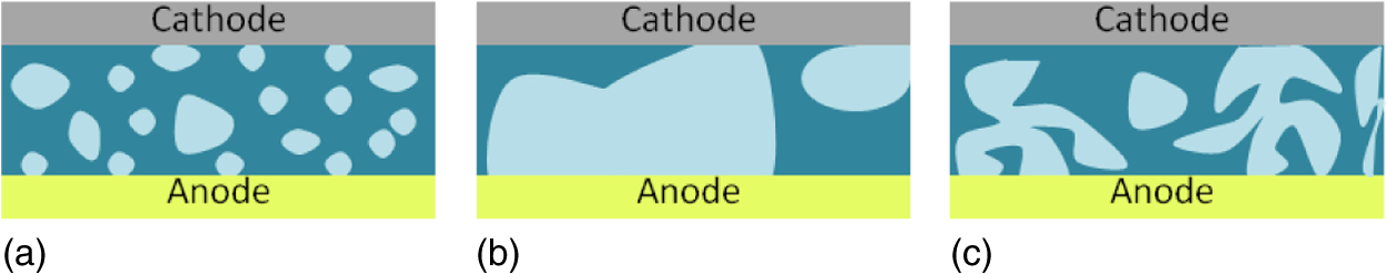 Solvent annealing, slow drying, and thermal annealing are few examples of how to deliberately influence the nanomorphology of the polymeric film.11–15 Additionally, the use of additives and different solvent mixtures has also been recently demonstrated as an easy and efficient approach to modify and control the morphology of the photoactive layer.16–18,44 3.1.Use of AdditivesAdditives are used for the generation of a more favorable nanomorphology for the transport of electrons and holes, thereby enhancing the final efficiency of the device. Additives do not react with the polymer or with the fullerene; the only aim is to favor the bicontinuous percolation pathways for exciton dissociation and charge transport. Two basic requirements for the correct choice of an additive are (1) the boiling point of the additive has to be much higher than the primary solvent and (2) only one component will be selectively dissolved in the additive. For example, considering polymer:fullerene blends, only the fullerene is selectively dissolved in the selected additive.17 Some of the most studied additives are based on alkanedithiols. Due to the ability of alkanedithiols to selectively dissolve the fullerene component while the polymer is less soluble, an optimum nanomorphology is formed.17 Peet et al. compared the performance of P3HT and PCPDTBT devices processed from pristine solvents and with blends of the same primary solvent and different alkanedithiols. They reported improvements in the PCE from 2.8 to 5.5% when 1,8-octanedithiol was added to chlorobenzene (CB).40 1,8-di(R)octanes with different functional groups (R) are also often used as additives in order to favor the nanomorphology of the film, which improves device efficiency. Figure 6 represents the influence of DIO on the final morphology of the film. When no additives are used, there are big aggregates of fullerene and the penetration of the acceptor molecules in the polymer network is more difficult, resulting in large fullerene and polymer domains. On the contrary, DIO is a much better solvent for the fullerene than CB while the polymer has limited solubility in DIO and is very well dissolved in CB. With the addition of DIO in this case, the fullerene is selectively dissolved, facilitating the percolation of acceptor molecules in the polymer network, resulting in a more favorable nanomorphology of the film due to the optimization of the domain size and polymer:fullerene interface.18 Fig. 6Graphical sketch of polymer and fullerene when using only chlorobenzene as a solvent (a) and with diiodooctane as an additive (b).18 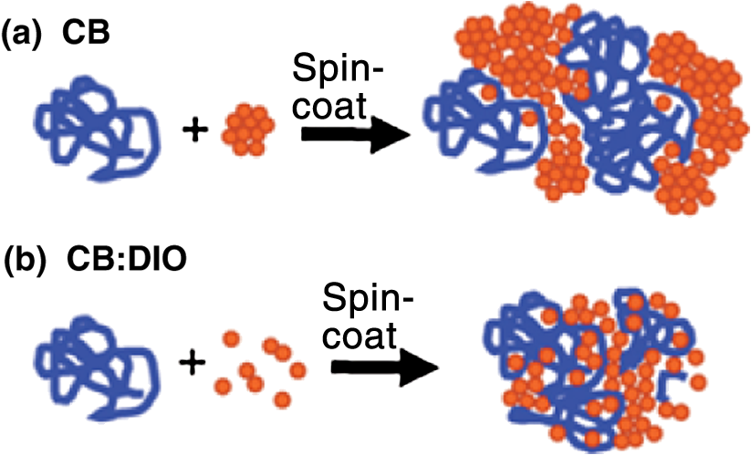 The work carried out by Liang et al. for devices based on PTB7 show the influence of DIO on device performance when using it as additive.55 Preliminary studies showed that () films prepared from ODCB and DIO (97%:3% in volume) increased the FF from 60.25 to 68.9% and the PCE from 6.22 to 7.18%, in comparison to devices processed from pristine ODCB. In this case, the photocurrent remained constant. However, when CB was used as the primary solvent, a considerable increment was also observed in the photocurrent (from 10.2 to ). Also, the FF rose from 50.52 to . In this way, it was possible to improve the efficiency from 3.92% (when CB was used as solvent) up to 7.4% when DIO was used as an additive. All these data are collected in Table 1. They also studied the influence of the additive on the morphology of the active layer by transmission electron microscopy. Images revealed that DIO promotes the formation of smaller domains. The film also showed a higher uniformity due to the good miscibility between PTB7 and and the formation of an interpenetrating network. In this way, higher FF and photocurrent values were achieved, thus increasing the PCE. Some other works have also shown the potential of DIO as an additive to improve the performance of devices made from different active materials. Lee et al. demonstrated an enhancement from 3.4 up to 5.1% by using DIO in BHJ organic solar cells based on systems.16 Zhang et al. reported a PCE increment from 1.4 to 4.8% when DIO was used as the additive to process devices from an LBG polymer consisting of thieno-thiophene substituted BDT (PTTBDT-C8).76 Finally, Bijleveld et al. also documented the use of DIO for processing devices with DPPs.29 They also observed an enhancement in the PCE from 2 to 5.6% and substantial changes in the film morphology when DIO was added to chloroform. 3.2.Solvent MixturesSimilarly to additives, the combination of two or more solvents with different boiling points and limited solubility for one of the components can help control the nanomorphology of the polymeric blend. Janssen et al. reported the influence of adding ODCB to chloroform in a series of DPP based device performance.44,77 The analysis was based on a narrow bandgap polymer known as pBBTDPP2, in combination with or diluted in chloroform (), ODCB, or a mixture of both solvents. When the polymer:fullerene was dissolved in chloroform, just 1.1% of PCE was achieved. This low performance was attributed to the amorphous nature of the deposited layer. When using ODCB instead, due to the limited solubility of pBBTDPP2 in this solvent, after spin-casting the solution, films with larger degrees of crystallinity were obtained, which resulted in devices with higher photocurrent values and, thus, higher PCEs, 2.9%. The PCE of pBBTDPP2 based devices was significantly improved by combining chloroform and ODCB. With the combination of these two solvents in a ratio of , a large amount of semicrystalline polymer film was obtained. In this way, PCE values of 3.2 and 4% were achieved when using and as electron acceptors, respectively. Due to the large difference in vapor pressure, the final film morphology was essentially determined by the slow evaporation of ODCB, leaving the polymer sufficient time to partly crystallize before precipitation. Cells from chloroform:ODCB, apart from higher photocurrent values, also provided higher FFs with respect to the other two options (see Table 2). Table 2Photovoltaic parameters of pBBTDPP2:PCBM solar cells.44
Zhang et al. also observed a significant enhancement in the photocurrent density for a polyfluorene copolymer/fullerene blend. When introducing a small amount of CB into the chloroform solvent, a uniform domain distribution was reached, resulting in more efficient devices.78 In further studies, 1-chloronaphthalene in ODCB or small amounts of nitrobenzene in CB have also been used as additives for P3HT:PCBM based devices in order to improve device performance with the aim of achieving a higher degree of crystallinity.79,80 3.3.Postprocessing TreatmentsThe possibility to act on film morphology during and after the deposition process has also been thoughtfully studied. First, it is possible to quite accurately control the drying time of the films by using alternative depositing techniques to spin-coating, as, for example, Dr. Blading. Based on the work carried out by Li et al. about the slow drying for film nanomorphology control in conventional architecture devices,11 Ajuria also slowed down the drying process of the P3HT:PCBM photoactive film in inverted configuration devices [600-nm-thick photoactive layer, see Fig. 7(a)].81 Film drying times were delayed from 1 to 2 s to and for films dried directly in air, protecting the film with a Petri dish as a lid in order to limit the contact of the film with air and create a solvent atmosphere below the Petri plate to minimize the presence of air, respectively. Fig. 7(a) Field emission scanning electron microscopy cross-sectional view of an inverted ITO/ZnO/P3HT:PCBM/PEDOT:PSS/Au solar cell. Different layers and their thickness are depicted. (b) curves of different photoactive layer drying techniques.81 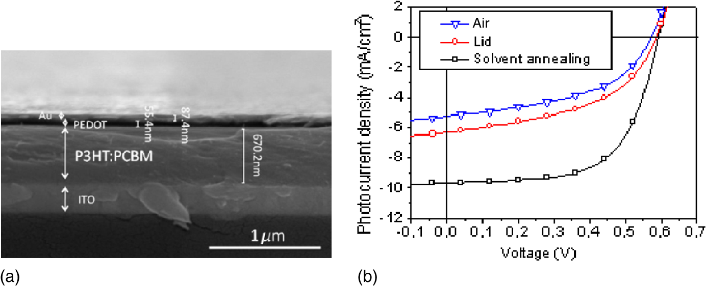 Results revealed that the slow drying of the film assists the growth of a photoactive self-ordered nanostructure, improving the PCE from 1.44 to 3.57% [see Fig. 7(b) and Table 3]. The self-organization of the polymer has been shown to improve field effect carrier mobilities by more than a factor of 100 in P3HT.82,83 On the contrary, the destruction of self-organized structures during fast drying (unordered growth) present unbalanced charge carriers and lower charge mobilities.11 Under these precisely controlled drying conditions, it is feasible to increase the thickness of the active film up to 600 nm, thus maximizing the light absorption without negatively affecting charge transport. Raising the Dr. Blade plate temperature from ambient conditions to 70°C had a similar effect. Table 3JV characteristics of different photoactive layer drying techniques.81
Alternatively, some other approaches to later manipulate the bulk morphology once the film has been already deposited from solution have been attempted with successful results. Zhou et al. spin-coated methanol on top of an already dry active layer comprising .84 They reported simultaneous improvements on device series resistance, charge mobility, charge recombination, and charge extraction mainly by means of surface modification. All these improvements gave rise to enhanced and FF, which lead to 7.9% PCE devices in comparison to 7.1% for nontreated films. Finally, a novel approach explores the viability of vapor printing as a fast postprocessing technique.85,86 A carrier gas transporting the vapor solvent is delivered through a nozzle promoting local self-assembly of polymer chains. This enables finding an optimal nanostructure in promisingly short times. Changes in the degree of crystallinity led to a twofold increase in PCE with respect to as-cast samples. 4.Device Layout/ArchitecturesAll the layers that form an organic solar cell have a direct influence on the performance of the device. Buffer interlayers are of crucial interest in order to increase the efficiency of devices. The working principles behind these—sometimes insulating materials—are not yet totally understood. Some of them are used to smooth out the rough profile of underlying films and avoid shunts. Others are used to modify the work function of the metal and align it to some extent with the HOMO and LUMO levels of the semiconductor, thus favoring an ohmic contact. Last but not least, ionic compounds are believed to form interfacial dipoles that help charge injection/extraction and, at the same time, generate optimal optical interferences that improve the light harvesting of devices.87,88 The device architecture can also alter the efficiency of an organic cell. In some cases, inverting the polarity of the cell can also have a positive influence on device performance due to vertical segregation of the mixed compounds that generate a more favorable donor and acceptor material concentration gradient, leading to a more efficient charge-transport process through the film.89,90 Moreover, the processing of more complicated architectures, such as tandem cells that comprise two connected cells made of polymers with complementary absorption spectra, can also result in high efficiency devices due to enhanced light absorption.19 All these device layout/architecture aspects that have a direct influence on the PCE of devices, but are not strictly related to either absorbers’ intrinsic properties or the nanomorphology of the film, will be addressed in this section. 4.1.Alternative InterlayersAn efficient charge extraction process following light absorption and charge generation requires the use of conducting electrodes wisely chosen in order to have energetic levels alignment and, hence, ideally ohmic contacts between the metal and the semiconductor, thus avoiding charge barriers and undesired losses. Depositing an extra buffer layer between the photoactive film and the metallic electrode has been demonstrated as an efficient way to improve the contact properties. Indium tin oxide (ITO) is typically used as the bottom contact (anode) in conventional configuration organic solar cells. ITO has a high work function around 4.8 eV, which is very dependent on washing treatments.91,92 However, these variations and the roughness of the resulting films usually result in important contact losses.93 In order to improve the quality of this contact and favor the formation of an ohmic contact, a p-type PEDOT:PSS interlayer, which has a work function of 5 eV, has been traditionally used.94 Due to the acidic nature of PEDOT:PSS and its tendency of being easily degraded in contact with either air or moisture and negatively affecting the stability of the whole device, different transition metal oxides, such as , , , and NiO, which are considered more stable, were introduced as alternative p-type interlayers in relatively highly efficient and stable devices.27,95,96 In the cathode side, instead, calcium was initially inherited from the organic light emitting diode (OLED) development as the hole blocking layer due to its low work function. In spite of the good results obtained for photovoltaic devices in combination with silver, it is, however, very reactive to oxygen and moisture and, thus, device stability is further jeopardized. Therefore, alternative inorganic low work function interlayers were introduced. On one side, inorganic salts, such as LiF,97–99 CsF,100,101 and MgF,102 have been vacuum evaporated in combination with aluminum in order to enhance the contact selectivity and, hence, the PCE. It is believed that due to their high internal dipole moment, thin layers of these materials are able to alter the electrode work function by inducing a shift of the vacuum energy level. Regardless of the increase in efficiency obtained with the use of these materials, they are principally vacuum deposited, which hinders the way toward lower-cost devices based on R2R processing. Solution processable alternatives make use of salts like ZnS,103 LiAc,104 or .105–107 Furthermore, polymeric salt compounds, known as polyelectrolytes, have been used with promising results.108 Also, small molecules with opposing internal charges, zwitterions, have been demonstrated as interfacial layers in organic solar cells.109,110 Khan et al. demonstrated efficient conventional configuration P3HT:ICBA based solar cells substituting the Ca layer with a thin film of a hydrophilic polymer processed from a polyethylenimine, 80% ethoxylated solution, PEIE.111 As a result, devices with a of 0.78 V, of , FF of 65%, and PCE of 4.6% were achieved. On the other side, as previously commented on for the anode, solution processable films of n-type inorganic semiconductors, such as and ZnO, processed from nanoparticle dispersions are typically used as n-type interlayers.112–115 Nowadays, many research groups, mainly motivated by the improvement observed in the FF and the parallel resistance, have focused their investigation on alternative interlayers that can further enhance the device’s overall performance. As it was shown in Sec. 3.1, Liang et al. improved the PCE of based organic solar cells from 3.92 to 7.40% by adding 3% of DIO to the primary solvent CB.55 However, more specifically related to the use of effective interlayers, further improvement was carried out by He et al. when a thin polymeric film of poly [(9,9-bis(3´-(N , N—dimethylamino) propyl)-2,7-fluorene)- alt -2,7-(9,9–dioctylfluorene)] (PFN) was incorporated as the cathode interlayer, increasing the PCE to 8.22%. Significant and simultaneous enhancements in , , and FF were observed.116 PFN is an alcohol/water soluble conjugated polymer that creates an interfacial dipole between the PFN and the polymeric blend. Moreover, the incorporation of PFN is believed to exert a strong electric field at the active layer/cathode interface, which may strongly influence charge transport and extraction. Thus, the effects of the interlayer on the improvement of device performance were due to improved charge-transport properties, reduction of any possible space charge effect at the interface, and reduced surface recombination losses.117 Regarding dipole formation at this interface and related to morphology issues, which were previously addressed in Sec. 3.3, it has been recently suggested that vertical segregation of the fullerene content toward the cathode can also result in interfacial dipoles of varying strength, which affect the selectivity of the contact in a similar way as buffer interlayers.118,119 Alternatively, Martínez-Otero et al. incorporated bathocuproine (BCP) as the interlayer of the cathode to achieve an optimal optical interference for PBDTTT-C and PTB7 based devices. As a result, for devices processed with BCP as the interlayer instead of Ca, an increment in PCE from 6.3 to 7.5% was observed for PBDTTT-C based cells and from 7.4 to 8.1% for the PTB7 based ones.88 In the case of PTB7, the increment in PCE was related to the increase in photocurrent due to the enhanced reflectivity of the buffer layer/electrode back contact. For the PBDTTT-C instead, apart from the photocurrent improvement, the FF was also enhanced from 60.3 to 67.9%, which was related to the reduction of recombination at the interfaces. 4.2.Inverted ConfigurationAs previously commented on at the beginning of Sec. 4, inverting the polarity of the device and processing the electron collecting electrode onto the ITO and the hole collection electrode on top of the active layer has also been successfully used to increase the efficiency of devices made with the same active materials. Ajuria et al. documented this effect for P3HT:PCBM devices for which impressive FFs were reported for inverted designs.120 In the case of PTB7 devices, further improvement in PCE was observed by He et al. when inverting the polarity of the device, reaching a very remarkable 9.2%.87 As it can be seen in Fig. 8 and Table 4, the efficiency improvement for inverted structure devices is mainly due to the larger with respect to the conventional one, in comparison to , respectively. The drastically enhanced for inverted devices was assigned to an improved ohmic contact, which eases photogenerated charge carrier collection and an optimum photon harvesting of these devices. Fig. 8Performance for inverted configuration (red filled symbols) () and conventional configuration (black open symbols) () devices. (a) Current density-voltage measurements and (b) external quantum efficiency (EQE) graph.87  Table 4Best device performance/parameters for PTB7:PC70BM based conventional and inverted solar cells with PFN as interlayer.87
CPVT, National Center of Supervision and Inspection on Solar Photovoltaic Products Quality of China. The interlayers used for inverted configurations can also be exposed to different treatments in order to modify their intrinsic properties and try to improve device efficiency. Adhikary et al. improved based inverted configuration devices from 6.46 to 8.34% by exposing the cell to UV-ozone.58 This treatment modifies the wurtzite phase crystallinity of the ZnO films, leading to faster film mobilities and improved charge extraction properties. While exposure times around 5 min resulted in an ideal crystalline structure, longer exposure times induced the formation of p-type defects, pushing the ZnO Fermi-level further away from the vacuum level and decreasing the wurtzite crystallinity. The work function of the materials can also be manipulated by surface modifiers. Zhou et al. demonstrated that compounds based on polymers containing simple aliphatic amine groups can substantially reduce the work function of conductors, including metals, transparent conductive metal oxides, conducting polymers, and graphene.121 Kyaw et al. incorporated PEIE on top of ZnO to enhance the efficiency of the cell by lowering the work function of ZnO (from 4.5 to 3.8 eV).122 With this surface modification, the PCE was enhanced from 6.29 to 7.88% thanks to simultaneous enhancements in , , and FF. 4.3.Tandem CellsThe main losses that occur in a solar cell are transmission and thermalization losses [see Fig. 9(a)]. Photons with lower energy than the energy bandgap will not be able to generate excited states, resulting in transmission losses. On the contrary, photons with energies larger than the energy bandgap will generate hot charge carriers that will relax down to the LUMO of the polymer, giving rise to thermalization losses.7,123–125 By stacking together in the same device two cells with polymers that absorb at different wavelengths, i.e., wide- and low-bandgap polymers, these losses can be reduced. The reduction in thermalization losses can be carried out by conversion in the subcell with a wide-bandgap polymer. On the other hand, transmission losses are lowered by absorption of the low energy photons in the subcell with a small-bandgap polymer. This results in polymer solar cells with ideally enhanced power conversion efficiencies. Fig. 9(a) Thermodynamic losses related to light absorption. (b) Layout of an organic tandem cell with two devices stacked one on top of another. 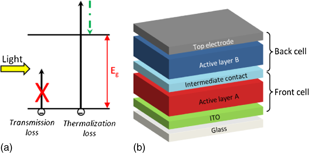 Tandem solar cells basically consist of stacking two or more devices one on top the each other with an adequate interlayer between them [see Fig. 9(b)]. The first deposited subcell is usually referred to as the front cell, while the one that is deposited on top is referred as the back cell. The connection among the subcells can be performed either in series (two terminals) or in parallel (three terminals).125–127 The front layer should ideally absorb only most of the light corresponding to wavelengths of its maximum absorption coefficient. On the contrary, the light that is not absorbed by the front cell, belonging to wavelengths of maximum absorption of the second layer, will be more efficiently absorbed by the polymer of the back cell. Thus, the solar irradiance is absorbed in a more efficient manner without the need of thick layers that can induce charge transport losses. Simple models have been developed for organic tandem devices in order to predict the efficiency increase when going from single to tandem cells. These models are based on the energy bandgaps of the absorbers used in each subcell and efficiencies up to 15% are estimated with the appropriate combination of materials.128,129 One of the first reports about organic tandem solar cells with two identical small molecule subcells stacked together separated by a thin gold layer was published in 1990 by Hiramoto et al.130 However, due to the limited choice of small molecule materials with significantly different absorption spectra, they started exploring hybrid tandem cells combining polymer and small molecule subcells.131–135 In 2005, Kawano et al. reported the first tandem cells composed of two identical polymer BHJ subcells stacked together with an interlayer comprising sputtered ITO and spin-coated PEDOT:PSS.136 One year later, Hadipour et al. showed a tandem cell consisting of subcells based on low- and wide-bandgap polymers with complementary absorptions.137 However, all these attempts resulted in efficiencies and many times even below those efficiencies reported for single cells made with one of the same comprising materials. A major breakthrough in the area of polymeric tandem cells was the demonstration of all solution processable polymer tandem cells with efficiency by Kim et al.138 More recently, in 2010, Gilot et al. studied the effect of current matching on the tandem device performance, which provides more insight in order to achieve high-performance tandem cells.139 It is worth saying that the performance of polymeric tandem cells during the last four years has been limited to mainly due to the lack of high-performing low-bandgap polymers.139–142 Nevertheless, in 2012, Dou et al. designed a new LBG polymer and achieved an inverted configuration tandem device with 8.6% PCE.143,144 Recently, Li et at. demonstrated tandem and triple-junction polymer solar cells with power conversion efficiencies of 8.9 and 9.6%, respectively, by combining an LBG polymer known as PMDPP3T (with absorption in the near-infrared region up to 960 nm) and the wide-bandgap polymer PCDTBT.20 Single cells based on and result in devices of 6 and 4.7% PCE, respectively. However, using the same layer thicknesses and stacking the subcells in a tandem cell [see Fig. 10(a)], the PCE was enhanced to 8.9%. Further improvement in the efficiency of the organic solar cell was carried out by adding an additional layer of the same small-bandgap material, creating a triple-junction device, as the one depicted in Fig. 10(d). In a tandem cell, the is limited by the wide-bangap front cell. However, this limitation is circumvented by splitting the small-bandgap subcell into two separate cells (middle and back cell) with different thicknesses to ensure that both absorb the same number of photons. The increase in of the triple junction (2.09 V with respect to 1.49 V) compensates the loss in [compare Figs. 10(b) and 10(c) with Figs. 10(e) and 10(f)]. In this way, the efficiency was enhanced up to 9.6%.20 Fig. 10Tandem and triple junction device layout [(a) and (d)], characteristics [(b) and (e)], and EQE graph [(c) and (f)].20 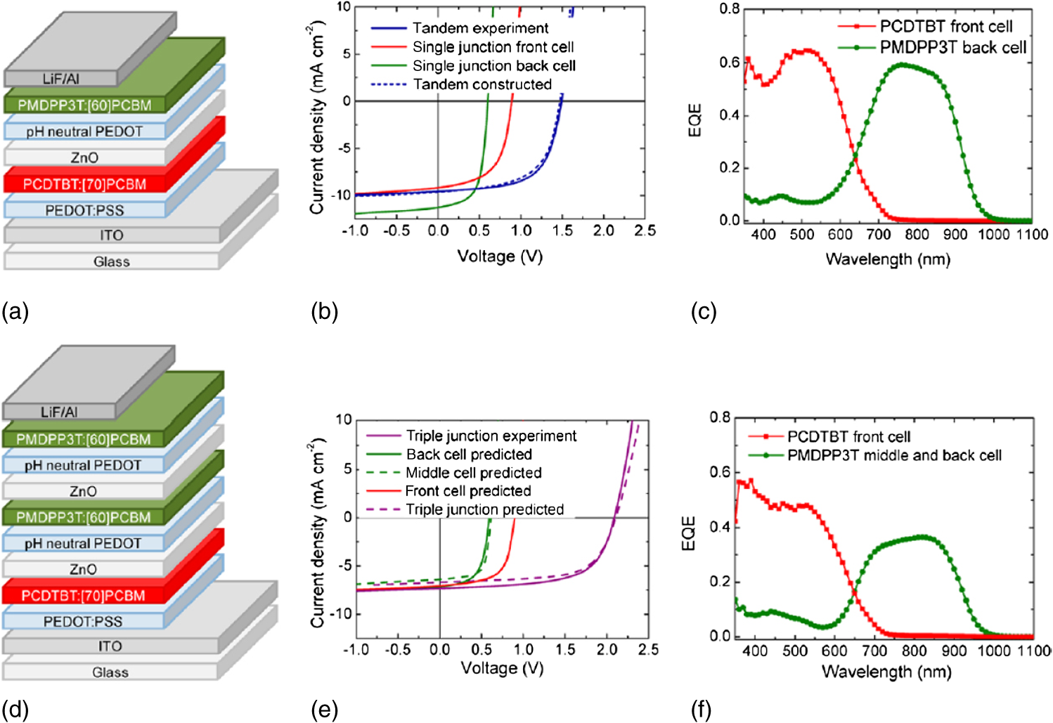 Efficiencies up to 10.2% have been published by You et al. by stacking together in a tandem device two identical subcells based on .145 It is worth mentioning that single based devices provide efficiencies of 8.1%. The absorption in the visible part of the tandem cell was significantly increased from 70 to 90% with respect to that of the single cell, suggesting that the performance of single cells for this material is a difficult compromise between light absorption and charge transport. Films of 80 nm are not able to absorb all the light; thicker films of 120 nm yield higher photocurrents () but smaller FF (58%) than those for thinner films of 80 nm ( and 65%, respectively). When implemented in a tandem configuration, however, it is preferred to have efficient charge transport since the lack of absorption of thinner films can be compensated by the extra absorption of the second cell that additionally offers a gain in . The best polymer-fullerene tandem solar cells have a reported certified efficiency of 10.6% [see Fig. 11(b)] and feature a response up to 900 nm.19 A wide-bandgap polymer, P3HT, was blended with ICBA in the front cell. As commented previously, this combination allows for a larger in comparison to more standard fullerene derivatives. The LBP PDTP-DFBT was used with either or as the back cell [see Fig. 11(a)]. In Table 5, the detailed parameters of single and tandem cells are summarized. As can be seen, single cells provide efficiencies of 6.1 and 7.1% for P3HT:ICBA and , respectively. It is remarkable that although the use of with the LBG material shows higher efficiencies than in single cells, thanks to the extended absorption of the former in comparison to the latter, this is not the case when implemented in tandem configuration. Either the front active film already absorbs at those wavelengths at which can represent an improvement with respect to and/or the extra current of the back cell breaks the current matching between the front and the back cell. The photocurrent of the tandem is obviously limited by the subcell with the lowest value. This is clearly the case for the tandem that makes use of in the back cell, whose photocurrent is very similar to that measured for an equivalent single cell of the front cell. However, when is used, the currents of both cells are unbalanced and penalize the overall performance of the tandem with additional losses that result in a photocurrent even lower than that of the limiting subcell. The is the perfect summation of each subcell, resulting in the most efficient reported tandem device to date. Fig. 11(a) Device structure of the tandem solar cell. (b) characteristics of the tandem cell as measured by NREL.19 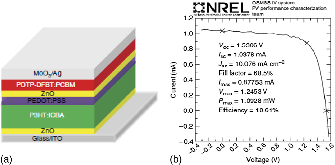 Table 5Poly(3-hexylthiophene) (P3HT) and PDTP-difluorobenzothiadiazole (DFBT) single junction cell and tandem solar cell performance.19
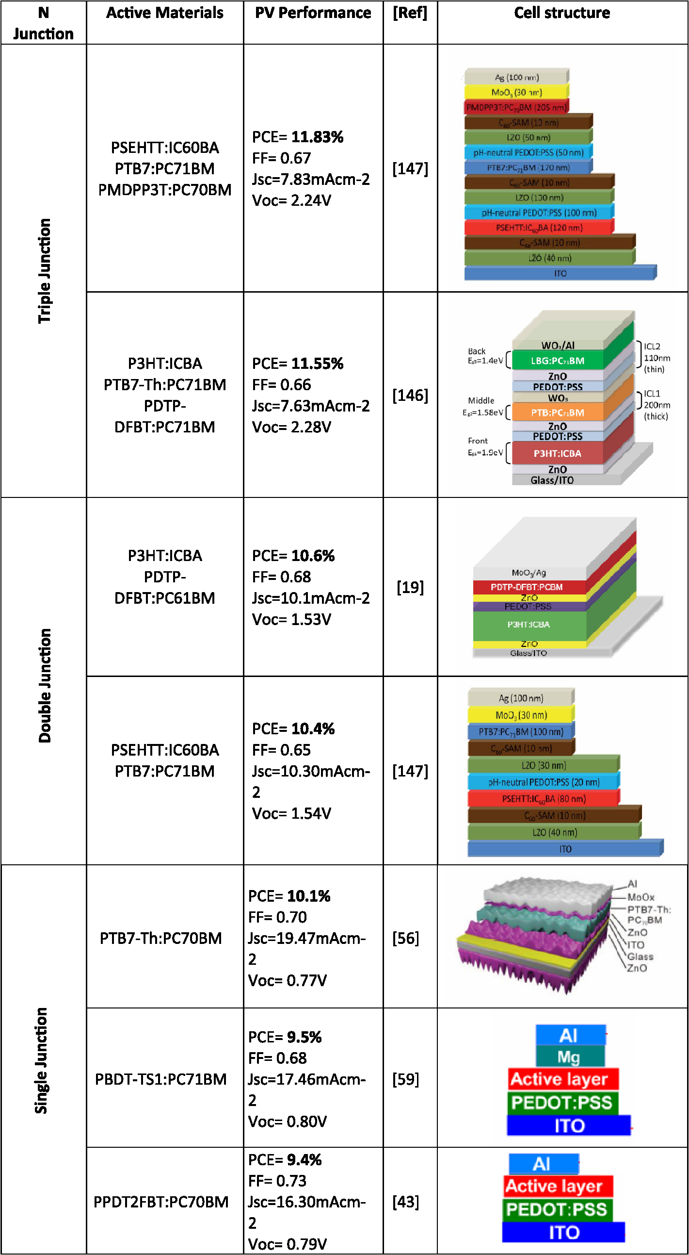
Note: ICBA, indene-C60 bis-adduct. Even though, as commented before, triple-junction devices can in some cases minimally improve the performance of tandem cells,20 they are very difficult and costly to implement. The enhancement obtained in terms of efficiency does not always compensate these two issues and one has to carefully analyze whether this approach is worth taking into account for a potential mass production. In any case, and considering only efficiency issues, an efficient triple-junction tandem organic solar cell with a record conversion efficiency of 11.5% has been recently published.146 Three complementary absorbers with bandgap energies from 1.4 to 1.9 eV are used to obtain balanced absorption rates and matched photocurrents among the three subcells. In similar terms, Yusoff et al. made use of a combination of a wide-bandgap, a medium-bandgap, and low-bandgap materials to report double-junction devices of 10.4% and a record efficiency of 11.83% for a triple-junction cell.147 The wide-bandgap material was a copolymer based on the alternation of dithienolsilole, thiophene, and thiazolothiazole segments (PSEHTT), whose bandgap lies at 1.82 eV, while the medium- and low-bandgap materials were the already introduced PTB7 (1.6 eV) and PMDPP3T (1.3 eV), respectively. Apart from the active materials, this work also makes use of all the other concepts mentioned in the other sections of this review, introducing, for example, new interlayers based on lithium zinc oxide and C60 self-assembled monolayers. The resulting devices show an impressive of 10.30 and , FF of 65.5 and 67.5, and of 1.54 and 2.24 V for the tandem () and triple device (), respectively. 5.SummaryIn this paper, we have initially presented the fundamental limits of polymeric solar cells, the factors that limit their performance, and the different possible approaches to maximize this. We have then offered a comprehensive and detailed review of the most efficient attempts to overcome the long ambitioned 10% PCE in polymeric devices. We have divided the development of polymeric solar cells in three categories indicating the most efficient efficiencies achieved for every case:
All these concepts and highlights are summarized in Fig. 12. AcknowledgmentsWe thank the European Community’s Seventh Framework Programme (FP72007-2013) under Grant Nos. 287818 and 604397 of the X10D and ARTESUN projects, respectively, for providing financial support. ReferencesJ. Nelson, The Physics of Solar Cells, Imperial College Press, Covent Garden, London
(2003). Google Scholar
M. C. Scharber and N. S. Sariciftci,
“Efficiency of bulk-heterojunction organic solar cells,”
Prog. Polym. Sci., 38 1929
–1940
(2013). http://dx.doi.org/10.1016/j.progpolymsci.2013.05.001 PRPSB8 0079-6700 Google Scholar
N. Li et al.,
“Environmentally printing efficient organic tandem solar cells with high fill factors: a guideline towards 20% power conversion efficiency,”
Adv. Energy Mater., 4
(11), 1400084
(2014). http://dx.doi.org/10.1002/aenm.201400084 ADEMBC 1614-6832 Google Scholar
C. J. Brabec et al.,
“Origin of the open circuit voltage of plastic solar cells,”
Adv. Funct. Mater., 11 374
–380
(2001). http://dx.doi.org/10.1002/(ISSN)1616-3028 AFMDC6 1616-3028 Google Scholar
M. Lenes et al.,
“Fullerene bisadducts for enhanced open-circuit voltages and efficiencies in polymer solar cells,”
Adv. Mater., 20 2116
–2119
(2008). http://dx.doi.org/10.1002/(ISSN)1521-4095 ADVMEW 0935-9648 Google Scholar
F. B. Kooistra et al.,
“Increasing the open circuit voltage of bulk-heterojunction solar cells by raising the LUMO level of the acceptor,”
Org. Lett., 9 551
–554
(2007). http://dx.doi.org/10.1021/ol062666p ORLEF7 1523-7060 Google Scholar
G. Dennler, M. C. Scharber and C. J. Brabec,
“Polymer-fullerene bulk-heterojunction solar cells,”
Adv. Mater., 21 1323
–1338
(2009). http://dx.doi.org/10.1002/adma.v21:13 ADVMEW 0935-9648 Google Scholar
J. K. J. van Duren et al.,
“Low-bandgap polymer photovoltaic cells,”
Synth. Met., 121 1587
–1588
(2001). http://dx.doi.org/10.1016/S0379-6779(00)01307-2 SYMEDZ 0379-6779 Google Scholar
A. Dhanabalan et al.,
“Synthesis and characterization of a low bandgap conjugated polymer for bulk heterojunction photovoltaic cells,”
Adv. Funct. Mater., 11 255
–262
(2001). http://dx.doi.org/10.1002/(ISSN)1616-3028 AFMDC6 1616-3028 Google Scholar
T. Stübinger and W. Brütting,
“Exciton diffusion and optical interference in organic donor-acceptor photovoltaic cells,”
J. Appl. Phys., 90 3632
–3641
(2001). http://dx.doi.org/10.1063/1.1394920 JAPIAU 0021-8979 Google Scholar
G. Li et al.,
“High-efficiency solution processable polymer photovoltaic cells by self-organization of polymer blends,”
Nat. Mater., 4 864
–868
(2005). http://dx.doi.org/10.1038/nmat1500 NMAACR 1476-1122 Google Scholar
W. Ma et al.,
“Thermally stable, efficient polymer solar cells with nanoscale control of the interpenetrating network morphology,”
Adv. Funct. Mater., 15 1617
–1622
(2005). http://dx.doi.org/10.1002/(ISSN)1616-3028 AFMDC6 1616-3028 Google Scholar
H. Hoppe and N. S. Sariciftci,
“Morphology of polymer/fullerene bulk heterojunction solar cells,”
J. Mater. Chem., 16 45
–61
(2006). http://dx.doi.org/10.1039/b510618b JMACEP 0959-9428 Google Scholar
S. Sam-Shajing et al.,
“Photovoltaic enhancement of organic solar cells by a bridged donor-acceptor block copolymer approach,”
Appl. Phys. Lett., 90 043117
(2007). http://dx.doi.org/10.1063/1.2437100 APPLAB 0003-6951 Google Scholar
S. Miller et al.,
“Investigation of nanoscale morphological changes in organic photovoltaics during solvent vapor annealing,”
J. Mater. Chem., 18 306
–312
(2008). http://dx.doi.org/10.1039/b713926h JMACEP 0959-9428 Google Scholar
J. K. Lee et al.,
“Processing additives for improved efficiency from bulk heterojunction solar cells,”
J. Am. Chem. Soc., 130 3619
–3623
(2008). http://dx.doi.org/10.1021/ja710079w JACSAT 0002-7863 Google Scholar
A. Pivrikas, H. Neugebauer and N. S. Sariciftci,
“Influence of processing additives to nano-morphology and efficiency of bulk-heterojunction solar cells: a comparative review,”
Sol. Energy, 85 1226
–1237
(2011). http://dx.doi.org/10.1016/j.solener.2010.10.012 SRENA4 0038-092X Google Scholar
S. J. Lou et al.,
“Effects of additives on the morphology of solution phase aggregates formed by active layer components of high-efficiency organic solar cells,”
J. Am. Chem. Soc., 133 20661
–20663
(2011). http://dx.doi.org/10.1021/ja2085564 JACSAT 0002-7863 Google Scholar
J. You et al.,
“A polymer tandem solar cell with 10.6% power conversion efficiency,”
Nat. Commun., 4 1446
(2013). http://dx.doi.org/10.1038/ncomms2411 NCAOBW 2041-1723 Google Scholar
W. Li et al.,
“Efficient tandem and triple-junction polymer solar cells,”
J. Am. Chem. Soc., 135 5529
–5532
(2013). http://dx.doi.org/10.1021/ja401434x JACSAT 0002-7863 Google Scholar
E. Bundgaard and F. C. Krebs,
“Low band gap polymers for organic photovoltaics,”
Sol. Energy Mater. Sol. Cells, 91 954
–985
(2007). http://dx.doi.org/10.1016/j.solmat.2007.01.015 SEMCEQ 0927-0248 Google Scholar
Y.-J. Cheng, S.-H. Yang and C.-S. Hsu,
“Synthesis of conjugated polymers for organic solar cell applications,”
Chem. Rev., 109 5868
–5923
(2009). http://dx.doi.org/10.1021/cr900182s CHREAY 0009-2665 Google Scholar
M. T. Dang, L. Hirsch and G. Wantz,
“P3HT:PCBM, best seller in polymer photovoltaic research,”
Adv. Mater., 23 3597
–3602
(2011). http://dx.doi.org/10.1002/adma.201100792 ADVMEW 0935-9648 Google Scholar
Y. Kim et al.,
“A strong regioregularity effect in self-organizing conjugated polymer films and high-efficiency polythiophene:fullerene solar cells,”
Nat. Mater., 5 197
–203
(2006). http://dx.doi.org/10.1038/nmat1574 NMAACR 1476-1122 Google Scholar
F. C. Krebs et al.,
“Large area plastic solar cell modules,”
Mater. Sci. Eng. B, 138 106
–111
(2007). http://dx.doi.org/10.1016/j.mseb.2006.06.008 MSBTEK 0921-5107 Google Scholar
F. C. Krebs et al.,
“Strategies for incorporation of polymer photovoltaics into garments and textiles,”
Sol. Energy Mater. Sol. Cells, 90 1058
–1067
(2006). http://dx.doi.org/10.1016/j.solmat.2005.06.003 SEMCEQ 0927-0248 Google Scholar
Y. Sun et al.,
“Efficient, air-stable bulk heterojunction polymer solar cells using MoOx as the anode interfacial layer,”
Adv. Mater., 23 2226
–2230
(2011). http://dx.doi.org/10.1002/adma.v23.19 ADVMEW 0935-9648 Google Scholar
S. Beaupre and M. Leclerc,
“PCDTBT: en route for low cost plastic solar cells,”
J. Mater. Chem. A, 1 11097
–11105
(2013). http://dx.doi.org/10.1039/c3ta12420g JMACEP 0959-9428 Google Scholar
J. C. Bijleveld et al.,
“Efficient solar cells based on an easily accessible diketopyrrolopyrrole polymer,”
Adv. Mater., 22 E242
–E246
(2010). http://dx.doi.org/10.1002/adma.201001449 ADVMEW 0935-9648 Google Scholar
H. Bronstein et al.,
“Thieno[3,2-b]thiophene-diketopyrrolopyrrole-containing polymers for high-performance organic field-effect transistors and organic photovoltaic devices,”
J. Am. Chem. Soc., 133 3272
–3275
(2011). http://dx.doi.org/10.1021/ja110619k JACSAT 0002-7863 Google Scholar
Y. Liang et al.,
“Development of new semiconducting polymers for high performance solar cells,”
J. Am. Chem. Soc., 131 56
–57
(2009). http://dx.doi.org/10.1021/ja808373p JACSAT 0002-7863 Google Scholar
Y. Liang et al.,
“Highly efficient solar cell polymers developed via fine-tuning of structural and electronic properties,”
J. Am. Chem. Soc., 131 7792
–7799
(2009). http://dx.doi.org/10.1021/ja901545q JACSAT 0002-7863 Google Scholar
X. Guo et al.,
“Influence of D/A ratio on photovoltaic performance of a highly efficient polymer solar cell system,”
Adv. Mater., 24 6536
–6541
(2012). http://dx.doi.org/10.1002/adma.v24.48 ADVMEW 0935-9648 Google Scholar
N. Blouin, A. Michaud and M. Leclerc,
“A low-bandgap poly(2,7-carbazole) derivative for use in high-performance solar cells,”
Adv. Mater., 19 2295
–2300
(2007). http://dx.doi.org/10.1002/(ISSN)1521-4095 ADVMEW 0935-9648 Google Scholar
N. Blouin et al.,
“Toward a rational design of poly(2,7-carbazole) derivatives for solar cells,”
J. Am. Chem. Soc., 130 732
–742
(2008). http://dx.doi.org/10.1021/ja0771989 JACSAT 0002-7863 Google Scholar
S. Alem et al.,
“Effect of mixed solvents on PCDTBT:PC70BM based solar cells,”
Org. Electron., 12 1788
–1793
(2011). http://dx.doi.org/10.1016/j.orgel.2011.07.011 1566-1199 Google Scholar
S. H. Park et al.,
“Bulk heterojunction solar cells with internal quantum efficiency approaching 100%,”
Nat. Photon., 3 297
–302
(2009). http://dx.doi.org/10.1038/nphoton.2009.69 1749-4885 Google Scholar
J. S. Moon, J. Jo and A. J. Heeger,
“Nanomorphology of bulk heterojunction solar cells,”
Adv. Energy Mater., 2 304
–308
(2012). http://dx.doi.org/10.1002/aenm.201100667 ADEMBC 1614-6832 Google Scholar
D. H. Wang et al.,
“Transferable graphene oxide by stamping nanotechnology: electron-transport layer for efficient bulk-heterojunction solar cells,”
Angew. Chem. Int. Ed., 52 2874
–2880
(2013). http://dx.doi.org/10.1002/anie.201209999 ACIEF5 1433-7851 Google Scholar
J. Peet et al.,
“Efficiency enhancement in low-bandgap polymer solar cells by processing with alkane dithiols,”
Nat. Mater., 6 497
–500
(2007). http://dx.doi.org/10.1038/nmat1928 NMAACR 1476-1122 Google Scholar
S. Albrecht et al.,
“Fluorinated copolymer PCPDTBT with enhanced open-circuit voltage and reduced recombination for highly efficient polymer solar cells,”
J. Am. Chem. Soc., 134 14932
–14944
(2012). http://dx.doi.org/10.1021/ja305039j JACSAT 0002-7863 Google Scholar
L. Dou et al.,
“Synthesis of 5H-dithieno[3,2-b:2’,3’-d]pyran as an electron-rich building block for donor-acceptor type low-bandgap polymers,”
Macromolecules, 46 3384
–3390
(2013). http://dx.doi.org/10.1021/ma400452j MAMOBX 0024-9297 Google Scholar
T. L. Nguyen et al.,
“Semi-crystalline photovoltaic polymers with efficiency exceeding 9% in a [similar]300 nm thick conventional single-cell device,”
Energy Environ. Sci., 7 3040
–3051
(2014). http://dx.doi.org/10.1039/C4EE01529K 1754-5692 Google Scholar
M. M. Wienk et al.,
“Narrow-bandgap diketo-pyrrolo-pyrrole polymer solar cells: the effect of processing on the performance,”
Adv. Mater., 20 2556
–2560
(2008). http://dx.doi.org/10.1002/adma.v20:13 ADVMEW 0935-9648 Google Scholar
B. Walker et al.,
“Nanoscale phase separation and high photovoltaic efficiency in solution-processed, small-molecule bulk heterojunction solar cells,”
Adv. Funct. Mater., 19 3063
–3069
(2009). http://dx.doi.org/10.1002/adfm.v19:19 AFMDC6 1616-3028 Google Scholar
L. Huo et al.,
“Bandgap and molecular level control of the low-bandgap polymers based on 3,6-dithiophen-2-yl-2,5-dihydropyrrolo[3,4-c]pyrrole-1,4-dione toward highly efficient polymer solar cells,”
Macromolecules, 42 6564
–6571
(2009). http://dx.doi.org/10.1021/ma9012972 MAMOBX 0024-9297 Google Scholar
J. Jo et al.,
“Bulk heterojunction solar cells based on a low-bandgap carbazole-diketopyrrolopyrrole copolymer,”
Appl. Phys. Lett., 97 203303
(2010). http://dx.doi.org/10.1063/1.3508951 APPLAB 0003-6951 Google Scholar
J. Ajuria et al.,
“Nanomorphology influence on the light conversion mechanisms in highly efficient diketopyrrolopyrrole based organic solar cells,”
Org. Electron., 14 326
–334
(2013). http://dx.doi.org/10.1016/j.orgel.2012.11.010 1566-1199 Google Scholar
J. Li et al.,
“Design and modification of three-component randomly incorporated copolymers for high performance organic photovoltaic applications,”
Polym. Chem., 4 804
–811
(2013). http://dx.doi.org/10.1039/c2py20763j ACPPAY 0032-3934 Google Scholar
H. Bronstein et al.,
“Thieno[3,2-b]thiophene-diketopyrrolopyrrole containing polymers for inverted solar cells devices with high short circuit currents,”
Adv. Funct. Mater., 23 5647
–5654
(2013). http://dx.doi.org/10.1002/adfm.v23.45 AFMDC6 1616-3028 Google Scholar
J. W. Jung et al.,
“A high mobility conjugated polymer based on dithienothiophene and diketopyrrolopyrrole for organic photovoltaics,”
Energy Environ. Sci., 5 6857
–6861
(2012). http://dx.doi.org/10.1039/c2ee21149a 1754-5692 Google Scholar
K. H. Hendriks et al.,
“High-molecular-weight regular alternating diketopyrrolopyrrole-based terpolymers for efficient organic solar cells,”
Angew. Chem. Int. Ed., 52 8341
–8344
(2013). http://dx.doi.org/10.1002/anie.v52.32 ACIEF5 1433-7851 Google Scholar
I. Meager et al.,
“Photocurrent enhancement from diketopyrrolopyrrole polymer solar cells through alkyl-chain branching point manipulation,”
J. Am. Chem. Soc., 135 11537
–11540
(2013). http://dx.doi.org/10.1021/ja406934j JACSAT 0002-7863 Google Scholar
Y. Liang et al.,
“Development of new semiconducting polymers for high performance solar cells,”
J. Am. Chem. Soc., 131 56
–57
(2009). http://dx.doi.org/10.1021/ja808373p JACSAT 0002-7863 Google Scholar
Y. Liang et al.,
“For the bright future—bulk heterojunction polymer solar cells with power conversion efficiency of 7.4%,”
Adv. Mater., 22 E135
–E138
(2010). http://dx.doi.org/10.1002/adma.200903528 ADVMEW 0935-9648 Google Scholar
J.-D. Chen et al.,
“Single-junction polymer solar cells exceeding 10% power conversion efficiency,”
Adv. Mater.,
(2014). http://dx.doi.org/10.1002/adma.201404535 ADVMEW 0935-9648 Google Scholar
L. Huo et al.,
“Replacing alkoxy groups with alkylthienyl groups: a feasible approach to improve the properties of photovoltaic polymers,”
Angew. Chem. Int. Ed., 50 9697
–9702
(2011). http://dx.doi.org/10.1002/anie.201103313 ACIEF5 1433-7851 Google Scholar
P. Adhikary et al.,
“Enhanced charge transport and photovoltaic performance of solar cells via UV-ozone treatment,”
Nanoscale, 5 10007
–10013
(2013). http://dx.doi.org/10.1039/c3nr03355d 1556-276X Google Scholar
L. Ye et al.,
“Highly efficient 2D-conjugated benzodithiophene-based photovoltaic polymer with linear alkylthio side chain,”
Chem. Mater., 26 3603
–3605
(2014). http://dx.doi.org/10.1021/cm501513n CMATEX 0897-4756 Google Scholar
C. Cabanetos et al.,
“Linear side chains in benzo[1,2-b:4,5-b’]dithiophene-thieno[3,4-c]pyrrole-4,6-dione polymers direct self-assembly and solar cell performance,”
J. Am. Chem. Soc., 135 4656
–4659
(2013). http://dx.doi.org/10.1021/ja400365b JACSAT 0002-7863 Google Scholar
Y.-C. Chen et al.,
“Low-bandgap conjugated polymer for high efficient photovoltaic applications,”
Chem. Commun., 46 6503
–6505
(2010). http://dx.doi.org/10.1039/c0cc01087a CHCOFS 1364-548X Google Scholar
Y. Zhang et al.,
“Indacenodithiophene and quinoxaline-based conjugated polymers for highly efficient polymer solar cells,”
Chem. Mater., 23 2289
–2291
(2011). http://dx.doi.org/10.1021/cm200316s CMATEX 0897-4756 Google Scholar
C.-P. Chen, Y.-C. Chen and C.-Y. Yu,
“Increased open circuit voltage in a fluorinated quinoxaline-based alternating conjugated polymer,”
Polym. Chem., 4 1161
–1166
(2013). http://dx.doi.org/10.1039/c2py20798b ACPPAY 0032-3934 Google Scholar
C.-P. Chen and H.-L. Hsu,
“Increasing the open-circuit voltage in high-performance organic photovoltaic devices through conformational twisting of an indacenodithiophene-based conjugated polymer,”
Macromol. Rapid Commun., 34 1623
–1628
(2013). http://dx.doi.org/10.1002/marc.v34.20 MRCOE3 1521-3927 Google Scholar
Z. Fei et al.,
“Germaindacenodithiophene based low band gap polymers for organic solar cells,”
Chem. Commun., 48 2955
–2957
(2012). http://dx.doi.org/10.1039/c2cc17996b CHCOFS 1364-548X Google Scholar
Y. He et al.,
“Indene-C60 bisadduct: a new acceptor for high-performance polymer solar cells,”
J. Am. Chem. Soc., 132 1377
–1382
(2010). http://dx.doi.org/10.1021/ja908602j JACSAT 0002-7863 Google Scholar
G. Zhao, Y. He and Y. Li,
“6.5% efficiency of polymer solar cells based on poly(3-hexylthiophene) and indene-C60 bisadduct by device optimization,”
Adv. Mater., 22 4355
–4358
(2010). http://dx.doi.org/10.1002/adma.v22:39 ADVMEW 0935-9648 Google Scholar
Y.-J. Cheng et al.,
“Combination of indene-C60 bis-adduct and cross-linked fullerene interlayer leading to highly efficient inverted polymer solar cells,”
J. Am. Chem. Soc., 132 17381
–17383
(2010). http://dx.doi.org/10.1021/ja108259n JACSAT 0002-7863 Google Scholar
H. J. Bolink et al.,
“Martin, polymer solar cells based on diphenylmethanofullerenes with reduced sidechain length,”
J. Mater. Chem., 21 1382
–1386
(2011). http://dx.doi.org/10.1039/c0jm01160f JMACEP 0959-9428 Google Scholar
Y.-J. Cheng et al.,
“Di(4-methylphenyl)methano-C60 bis-adduct for efficient and stable organic photovoltaics with enhanced open-circuit voltage,”
Chem. Mater., 23 4056
–4062
(2011). http://dx.doi.org/10.1021/cm201784w CMATEX 0897-4756 Google Scholar
R. B. Ross et al.,
“Endohedral fullerenes for organic photovoltaic devices,”
Nat. Mater., 8 208
–212
(2009). http://dx.doi.org/10.1038/nmat2379 NMAACR 1476-1122 Google Scholar
R. B. Ross et al.,
“Tuning conversion efficiency in metallo endohedral fullerene-based organic photovoltaic devices,”
Adv. Funct. Mater., 19 2332
–2337
(2009). http://dx.doi.org/10.1002/adfm.v19:14 AFMDC6 1616-3028 Google Scholar
Y. Zhou et al.,
“High performance all-polymer solar cell via polymer side-chain engineering,”
Adv. Mater., 26 3767
–3772
(2014). http://dx.doi.org/10.1002/adma.v26.22 ADVMEW 0935-9648 Google Scholar
Y. Kim and E. Lim,
“Development of polymer acceptors for organic photovoltaic cells,”
Polymers, 6 382
–407
(2014). http://dx.doi.org/10.3390/polym6020382 2073-4360 Google Scholar
H. Hoppe et al.,
“Nanoscale morphology of conjugated polymer/fullerene-based bulk-heterojunction solar cells,”
Adv. Funct. Mater., 14 1005
–1011
(2004). http://dx.doi.org/10.1002/(ISSN)1616-3028 AFMDC6 1616-3028 Google Scholar
Y. Zhang et al.,
“Bulk heterojunction solar cells based on a new low-band-gap polymer: morphology and performance,”
Org. Electron., 12 1211
–1215
(2011). http://dx.doi.org/10.1016/j.orgel.2011.04.001 1566-1199 Google Scholar
W. Li et al.,
“Efficient small bandgap polymer solar cells with high fill factors for 300 nm thick films,”
Adv. Mater., 25 3182
–3186
(2013). http://dx.doi.org/10.1002/adma.201300017 ADVMEW 0935-9648 Google Scholar
F. Zhang et al.,
“Influence of solvent mixing on the morphology and performance of solar cells based on polyfluorene copolymer/fullerene blends,”
Adv. Funct. Mater., 16 667
–674
(2006). http://dx.doi.org/10.1002/(ISSN)1616-3028 AFMDC6 1616-3028 Google Scholar
F.-C. Chen, H.-C. Tseng and C.-J. Ko,
“Solvent mixtures for improving device efficiency of polymer photovoltaic devices,”
Appl. Phys. Lett., 92 103316
(2008). http://dx.doi.org/10.1063/1.2898153 APPLAB 0003-6951 Google Scholar
A. J. Moulé and K. Meerholz,
“Controlling morphology in polymer–fullerene mixtures,”
Adv. Mater., 20 240
–245
(2008). http://dx.doi.org/10.1002/(ISSN)1521-4095 ADVMEW 0935-9648 Google Scholar
J. Ajuria,
“Hybrid photovoltaic devices based on organic semiconducting polymers and inorganic nanostructured electrodes,”
Euskal Herriko Unibertsitatea (UPV/EHU),
(2012). Google Scholar
Z. Bao, A. Dodabalapur and A. J. Lovinger,
“Soluble and processable regioregular poly(3-hexylthiophene) for thin film field-effect transistor applications with high mobility,”
Appl. Phys. Lett., 69 4108
–4110
(1996). http://dx.doi.org/10.1063/1.117834 APPLAB 0003-6951 Google Scholar
H. Sirringhaus et al.,
“Two-dimensional charge transport in self-organized, high-mobility conjugated polymers,”
Nature, 401 685
–688
(1999). http://dx.doi.org/10.1038/44359 0028-0836 Google Scholar
H. Zhou et al.,
“High-efficiency polymer solar cells enhanced by solvent treatment,”
Adv. Mater., 25 1646
–1652
(2013). http://dx.doi.org/10.1002/adma.201204306 ADVMEW 0935-9648 Google Scholar
I. Burgués-Ceballos et al.,
“Fast annealing and patterning of polymer solar cells by means of vapor printing,”
J. Polym. Sci. B Polym. Phys., 50 1245
–1252
(2012). http://dx.doi.org/10.1002/polb.v50.17 JPLPAY 0887-6266 Google Scholar
D. Nassyrov et al.,
“Vapour printing: patterning of the optical and electrical properties of organic semiconductors in one simple step,”
J. Mater. Chem., 22 4519
–4526
(2012). http://dx.doi.org/10.1039/c2jm15190a JMACEP 0959-9428 Google Scholar
Z. He et al.,
“Enhanced power-conversion efficiency in polymer solar cells using an inverted device structure,”
Nat. Photon., 6 591
–595
(2012). http://dx.doi.org/10.1038/nphoton.2012.190 1749-4885 Google Scholar
A. Martínez-Otero et al.,
“High-performance polymer solar cells using an optically enhanced architecture,”
Adv. Opt. Mater., 1 37
–42
(2013). http://dx.doi.org/10.1002/adom.201200027 AOMDAX 2195-1071 Google Scholar
M. Campoy-Quiles et al.,
“Morphology evolution via self-organization and lateral and vertical diffusion in polymer:fullerene solar cell blends,”
Nat. Mater., 7 158
–164
(2008). http://dx.doi.org/10.1038/nmat2102 NMAACR 1476-1122 Google Scholar
L. M. Chen et al.,
“Recent progress in polymer solar cells: manipulation of polymer:fullerene morphology and the formation of efficient inverted polymer solar cells,”
Adv. Mater., 21 1434
–1449
(2009). http://dx.doi.org/10.1002/adma.v21:14/15 ADVMEW 0935-9648 Google Scholar
K. Sugiyama et al.,
“Dependence of indium-tin-oxide work function on surface cleaning method as studied by ultraviolet and x-ray photoemission spectroscopies,”
J. Appl. Phys., 87 295
–298
(2000). http://dx.doi.org/10.1063/1.371859 JAPIAU 0021-8979 Google Scholar
T. M. Brown et al.,
“Built-in field electroabsorption spectroscopy of polymer light-emitting diodes incorporating a doped poly(3,4-ethylene dioxythiophene) hole injection layer,”
Appl. Phys. Lett., 75 1679
–1681
(1999). http://dx.doi.org/10.1063/1.124789 APPLAB 0003-6951 Google Scholar
A. C. Arias et al.,
“Doped conducting-polymer-semiconducting-polymer interfaces: their use in organic photovoltaic devices,”
Phys. Rev. B, 60 1854
–1860
(1999). http://dx.doi.org/10.1103/PhysRevB.60.1854 PRBMDO 0163-1829 Google Scholar
A. J. Campbell et al.,
“Transient and steady-state space-charge-limited currents in polyfluorene copolymer diode structures with ohmic hole injecting contacts,”
Appl. Phys. Lett., 76 1734
–1736
(2000). http://dx.doi.org/10.1063/1.126182 APPLAB 0003-6951 Google Scholar
V. Shrotriya et al.,
“Transition metal oxides as the buffer layer for polymer photovoltaic cells,”
Appl. Phys. Lett., 88 073508
(2006). http://dx.doi.org/10.1063/1.2174093 APPLAB 0003-6951 Google Scholar
M. D. Irwin et al.,
“p-type semiconducting nickel oxide as an efficiency-enhancing anode interfacial layer in polymer bulk-heterojunction solar cells,”
Proc. Natl. Acad. Sci., 105 2783
–2787
(2008). http://dx.doi.org/10.1073/pnas.0711990105 PMASAX 0096-9206 Google Scholar
E. I. Haskal et al.,
“Lithium-aluminum contacts for organic light-emitting devices,”
Appl. Phys. Lett., 71 1151
–1153
(1997). http://dx.doi.org/10.1063/1.119850 APPLAB 0003-6951 Google Scholar
L. S. Hung, C. W. Tang and M. G. Mason,
“Enhanced electron injection in organic electroluminescence devices using an Al/LiF electrode,”
Appl. Phys. Lett., 70 152
–154
(1997). http://dx.doi.org/10.1063/1.118344 APPLAB 0003-6951 Google Scholar
J. Zhi-Qiang et al.,
“Improving efficiency of organic light-emitting devices by optimizing the LiF interlayer in the hole transport layer,”
Chin. Phys. B, 20 107803
(2011). http://dx.doi.org/10.1088/1674-1056/20/10/107803 1674-1056 Google Scholar
X. Jiang et al.,
“Effect of CsF interlayer on the performance of polymer bulk heterojunction solar cells,”
Sol. Energy Mater. Sol. Cells, 93 650
–653
(2009). http://dx.doi.org/10.1016/j.solmat.2009.01.005 SEMCEQ 0927-0248 Google Scholar
M. Reinhard et al.,
“Inverted organic solar cells comprising a solution-processed cesium fluoride interlayer,”
Appl. Phys. Lett., 98 053303
(2011). http://dx.doi.org/10.1063/1.3548860 APPLAB 0003-6951 Google Scholar
L. Ke et al.,
“Magnesium fluoride modified interfaces for organic light-emitting diode,”
Thin Solid Films, 515 3881
–3886
(2007). http://dx.doi.org/10.1016/j.tsf.2006.10.129 THSFAP 0040-6090 Google Scholar
T. Kuwabara et al.,
“Characterization of ZnS-layer-inserted bulk-heterojunction organic solar cells by ac impedance spectroscopy,”
J. Appl. Phys., 105 124513
(2009). http://dx.doi.org/10.1063/1.3153970 JAPIAU 0021-8979 Google Scholar
L. Jiang et al.,
“Effects of cathode modification using spin-coated lithium acetate on the performances of polymer bulk-heterojunction solar cells,”
Appl. Phys. Lett., 102 013303
(2013). http://dx.doi.org/10.1063/1.4773570 APPLAB 0003-6951 Google Scholar
F.-C. Chen et al.,
“Cesium carbonate as a functional interlayer for polymer photovoltaic devices,”
J. Appl. Phys., 103 103721
(2008). http://dx.doi.org/10.1063/1.2937202 JAPIAU 0021-8979 Google Scholar
H.-H. Liao et al.,
“Highly efficient inverted polymer solar cell by low temperature annealing of interlayer,”
Appl. Phys. Lett., 92 173303
(2008). http://dx.doi.org/10.1063/1.2918983 APPLAB 0003-6951 Google Scholar
Y. Park et al.,
“Study of the cesium carbonate () inter layer fabricated by solution process on P3HT:PCBM solar cells,”
Mol. Cryst. Liq. Cryst., 538 20
–27
(2011). http://dx.doi.org/10.1080/15421406.2011.563221 MCLCA5 0026-8941 Google Scholar
F. Huang, H. Wu and Y. Cao,
“Water/alcohol soluble conjugated polymers as highly efficient electron transporting/injection layer in optoelectronic devices,”
Chem. Soc. Rev., 39 2500
–2521
(2010). http://dx.doi.org/10.1039/b907991m CSRVBR 0306-0012 Google Scholar
K. Sun et al.,
“Highly efficient, inverted polymer solar cells with indium tin oxide modified with solution-processed zwitterions as the transparent cathode,”
ACS Appl. Mater. Interfaces, 4 2009
–2017
(2012). http://dx.doi.org/10.1021/am201844q AAMICK 1944-8244 Google Scholar
K. Sun et al.,
“High-performance polymer solar cells with a conjugated zwitterion by solution processing or thermal deposition as the electron-collection interlayer,”
J. Mater. Chem., 22 24155
–24165
(2012). http://dx.doi.org/10.1039/c2jm35221d JMACEP 0959-9428 Google Scholar
T. M. Khan et al.,
“Organic photovoltaic cells with stable top metal electrodes modified with polyethylenimine,”
ACS Appl. Mater. Interfaces, 6 6202
–6207
(2014). http://dx.doi.org/10.1021/am501236z AAMICK 1944-8244 Google Scholar
C. J. Brabec et al.,
“Effect of LiF/metal electrodes on the performance of plastic solar cells,”
Appl. Phys. Lett., 80 1288
–1290
(2002). http://dx.doi.org/10.1063/1.1446988 APPLAB 0003-6951 Google Scholar
J. Y. Kim et al.,
“New architecture for high-efficiency polymer photovoltaic cells using solution-based titanium oxide as an optical spacer,”
Adv. Mater., 18 572
–576
(2006). http://dx.doi.org/10.1002/(ISSN)1521-4095 ADVMEW 0935-9648 Google Scholar
M.-H. Park et al.,
“Doping of the metal oxide nanostructure and its influence in organic electronics,”
Adv. Funct. Mater., 19 1241
–1246
(2009). http://dx.doi.org/10.1002/adfm.v19:8 AFMDC6 1616-3028 Google Scholar
J. Gilot et al.,
“The use of ZnO as optical spacer in polymer solar cells: theoretical and experimental study,”
Appl. Phys. Lett., 91 113520
(2007). http://dx.doi.org/10.1063/1.2784961 APPLAB 0003-6951 Google Scholar
Z. He et al.,
“Simultaneous enhancement of open-circuit voltage, short-circuit current density, and fill factor in polymer solar cells,”
Adv. Mater., 23 4636
–4643
(2011). http://dx.doi.org/10.1002/adma.201103006 ADVMEW 0935-9648 Google Scholar
J. Reinhardt et al.,
“Identifying the impact of surface recombination at electrodes in organic solar cells by means of electroluminescence and modeling,”
Adv. Energy Mater., 4
(11), 1400081
(2014). http://dx.doi.org/10.1002/aenm.201400081 ADEMBC 1614-6832 Google Scholar
A. Guerrero et al.,
“Charge carrier transport and contact selectivity limit the operation of PTB7-based organic solar cells of varying active layer thickness,”
J. Mater. Chem. A, 1 12345
–12354
(2013). http://dx.doi.org/10.1039/c3ta12358h JMACEP 0959-9428 Google Scholar
A. Guerrero et al.,
“Interplay between fullerene surface coverage and contact selectivity of cathode interfaces in organic solar cells,”
ACS Nano, 7 4637
–4646
(2013). http://dx.doi.org/10.1021/nn4014593 1936-0851 Google Scholar
J. Ajuria et al.,
“Inverted ITO-free organic solar cells based on p and n semiconducting oxides. New designs for integration in tandem cells, top or bottom detecting devices, and photovoltaic windows,”
Energy Environ. Sci., 4 453
–458
(2011). http://dx.doi.org/10.1039/c0ee00318b 1754-5692 Google Scholar
Y. Zhou et al.,
“A universal method to produce low-work function electrodes for organic electronics,”
Science, 336 327
–332
(2012). http://dx.doi.org/10.1126/science.1218829 SCIEAS 0036-8075 Google Scholar
A. K. K. Kyaw et al.,
“Efficient solution-processed small-molecule solar cells with inverted structure,”
Adv. Mater., 25 2397
–2402
(2013). http://dx.doi.org/10.1002/adma.v25.17 ADVMEW 0935-9648 Google Scholar
W. Shockley and H. J. Queisser,
“Detailed balance limit of efficiency of p-n junction solar cells,”
J. Appl. Phys., 32 510
–519
(1961). http://dx.doi.org/10.1063/1.1736034 JAPIAU 0021-8979 Google Scholar
T. Ameri et al.,
“Organic tandem solar cells: a review,”
Energy Environ. Sci., 2 347
–363
(2009). http://dx.doi.org/10.1039/b817952b 1754-5692 Google Scholar
S. Sista et al.,
“Tandem polymer photovoltaic cells-current status, challenges and future outlook,”
Energy Environ. Sci., 4 1606
–1620
(2011). http://dx.doi.org/10.1039/c0ee00754d 1754-5692 Google Scholar
S. Sista et al.,
“High-efficiency polymer tandem solar cells with three-terminal structure,”
Adv. Mater., 22 E77
–E80
(2010). http://dx.doi.org/10.1002/adma.v22:8 ADVMEW 0935-9648 Google Scholar
I. Etxebarria et al.,
“Series vs parallel connected organic tandem solar cells: cell performance and impact on the design and operation of functional modules,”
Sol. Energy Mater. Sol. Cells, 130 495
–504
(2014). http://dx.doi.org/10.1016/j.solmat.2014.07.047 SEMCEQ 0927-0248 Google Scholar
M. C. Scharber et al.,
“Design rules for donors in bulk-heterojunction solar cells—towards 10% energy-conversion efficiency,”
Adv. Mater., 18 789
–794
(2006). http://dx.doi.org/10.1002/(ISSN)1521-4095 ADVMEW 0935-9648 Google Scholar
G. Dennler et al.,
“Design rules for donors in bulk-heterojunction tandem solar cells—towards 15% energy-conversion efficiency,”
Adv. Mater., 20 579
–583
(2008). http://dx.doi.org/10.1002/(ISSN)1521-4095 ADVMEW 0935-9648 Google Scholar
M. Hiramoto, M. Suezaki and M. Yokoyama,
“Effect of thin gold interstitial-layer on the photovoltaic properties of tandem organic solar cell,”
Chem. Lett., 19 327
–330
(1990). http://dx.doi.org/10.1246/cl.1990.327 CMLTAG 0366-7022 Google Scholar
G. Dennler et al.,
“Enhanced spectral coverage in tandem organic solar cells,”
Appl. Phys. Lett., 89 073502
(2006). http://dx.doi.org/10.1063/1.2336593 APPLAB 0003-6951 Google Scholar
A. Colsmann et al.,
“Organic tandem solar cells comprising polymer and small-molecule subcells,”
Appl. Phys. Lett., 89 203506
(2006). http://dx.doi.org/10.1063/1.2388938 APPLAB 0003-6951 Google Scholar
A. G. F. Janssen et al.,
“Highly efficient organic tandem solar cells using an improved connecting architecture,”
Appl. Phys. Lett., 91 073519
(2007). http://dx.doi.org/10.1063/1.2772208 APPLAB 0003-6951 Google Scholar
D. W. Zhao et al.,
“Efficient tandem organic solar cells with an intermediate layer,”
Appl. Phys. Lett., 93 083305
(2008). http://dx.doi.org/10.1063/1.2976126 APPLAB 0003-6951 Google Scholar
B. J. Lee et al.,
“A transparent conducting oxide as an efficient middle electrode for flexible organic tandem solar cells,”
Sol. Energy Mater. Sol. Cells, 94 542
–546
(2010). http://dx.doi.org/10.1016/j.solmat.2009.11.021 SEMCEQ 0927-0248 Google Scholar
K. Kawano et al.,
“Open circuit voltage of stacked bulk heterojunction organic solar cells,”
Appl. Phys. Lett., 88 073514
(2006). http://dx.doi.org/10.1063/1.2177633 APPLAB 0003-6951 Google Scholar
A. Hadipour et al.,
“Solution-processed organic tandem solar cells,”
Adv. Funct. Mater., 16 1897
–1903
(2006). http://dx.doi.org/10.1002/(ISSN)1616-3028 AFMDC6 1616-3028 Google Scholar
J. Y. Kim et al.,
“Efficient tandem polymer solar cells fabricated by all-solution processing,”
Science, 317 222
–225
(2007). http://dx.doi.org/10.1126/science.1141711 SCIEAS 0036-8075 Google Scholar
J. Gilot, M. M. Wienk and R. A. J. Janssen,
“Optimizing polymer tandem solar cells,”
Adv. Mater., 22 E67
–E71
(2010). http://dx.doi.org/10.1002/adma.v22:8 ADVMEW 0935-9648 Google Scholar
S. Sista et al.,
“Highly efficient tandem polymer photovoltaic cells,”
Adv. Mater., 22 380
–383
(2010). http://dx.doi.org/10.1002/adma.v22:3 ADVMEW 0935-9648 Google Scholar
J. Yang et al.,
“A robust inter-connecting layer for achieving high performance tandem polymer solar cells,”
Adv. Mater., 23 3465
–3470
(2011). http://dx.doi.org/10.1002/adma.201100221 ADVMEW 0935-9648 Google Scholar
C.-H. Chou et al.,
“A metal-oxide interconnection layer for polymer tandem solar cells with an inverted architecture,”
Adv. Mater., 23 1282
–1286
(2011). http://dx.doi.org/10.1002/adma.201001033 ADVMEW 0935-9648 Google Scholar
L. Dou et al.,
“Tandem polymer solar cells featuring a spectrally matched low-bandgap polymer,”
Nat. Photon., 6 180
–185
(2012). http://dx.doi.org/10.1038/nphoton.2011.356 1749-4885 Google Scholar
L. Dou et al.,
“Systematic investigation of benzodithiophene- and diketopyrrolopyrrole-based low-bandgap polymers designed for single junction and tandem polymer solar cells,”
J. Am. Chem. Soc., 134 10071
–10079
(2012). http://dx.doi.org/10.1021/ja301460s JACSAT 0002-7863 Google Scholar
J. You et al.,
“10.2% power conversion efficiency polymer tandem solar cells consisting of two identical sub-cells,”
Adv. Mater., 25 3973
–3978
(2013). http://dx.doi.org/10.1002/adma.v25.29 ADVMEW 0935-9648 Google Scholar
C.-C. Chen et al.,
“An efficient triple-junction polymer solar cell having a power conversion efficiency exceeding 11%,”
Adv. Mater., 26 5670
–5677
(2014). http://dx.doi.org/10.1002/adma.201402072 ADVMEW 0935-9648 Google Scholar
A. R. b. M. Yusoff et al.,
“A high efficiency solution processed polymer inverted triple-junction solar cell exhibiting a power conversion efficiency of 11.83%,”
Energy Environ. Sci., 8 303
–316
(2015). http://dx.doi.org/10.1039/C4EE03048F 1754-5692 Google Scholar
BiographyIkerne Etxebarria received her BSc degree in chemical engineering in 2009 and a master’s degree in new materials in 2010 from the University of the Basque Country. In 2014, she was awarded her PhD degree by the same university. At present, her main research activity is focused on surface functionalization by means of inkjet printing, on the one hand for photoactive layer patterning for OPV module fabrication and on the other for sensor applications. Jon Ajuria received his chemistry degree in 2003 from the University of the Basque Country. In 2007, he moved to IKERLAN to carry out his PhD thesis on hybrid organic-inorganic solar cells. He was awarded his PhD degree by the University of the Basque Country in 2012. At present, his main research focus in the development of inverted single and tandem solar cells based on new generation low band gap materials and inorganic nanostructured electrodes. Roberto Pacios graduated in physics from the University of the Basque Country, Spain, in 1999. He was awarded his PhD degree by Imperial College London in 2003. After a postdoctoral stay, he moved to Siemens in Erlangen, Germany. In 2006 he moved to the Microsystems Department of IK4-IKERLAN, where he leads activities in plastics electronics and organic photovoltaics. His research career has been focused on material characterization, device integration, and module development of polymer solar cells. |