|
|
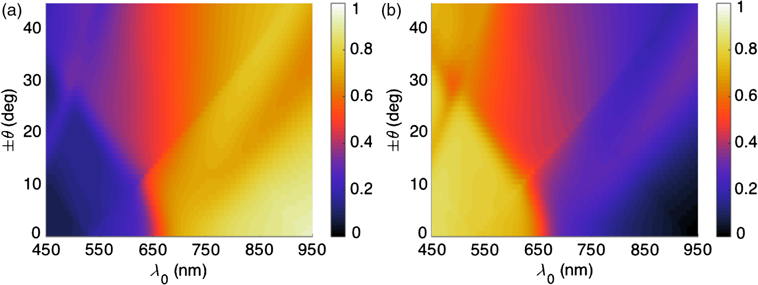
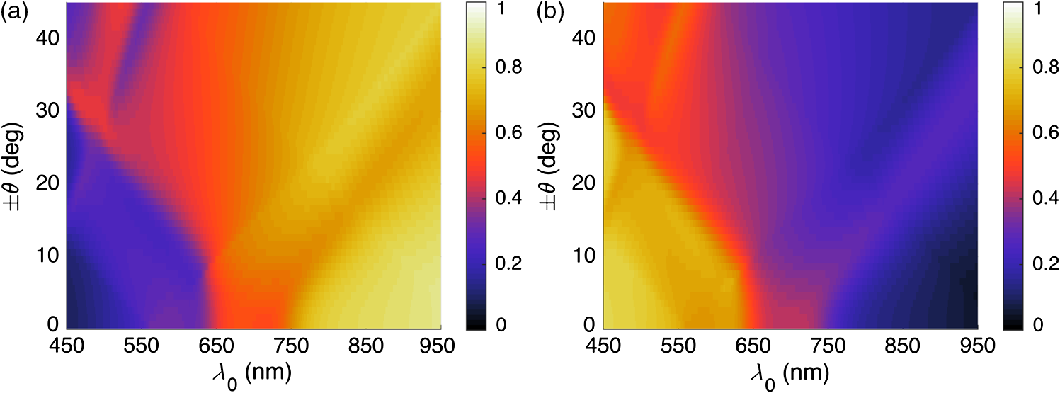
1.IntroductionThe efficiency of a solar cell varies with the (free-space) wavelength. Some semiconductors are more efficient harvesters of solar energy at longer wavelengths, others at shorter wavelengths.1 If the incident solar light could be split such that light below a cutoff wavelength is directed to a solar cell that is efficient in that spectral regime, while light at wavelengths above the cutoff wavelength is directed to another solar cell that is efficient in that spectral regime, then maximal harvesting of solar energy could become possible. So a spectrum splitter could be used to spatially multiplex different solar cells that have high efficiency in mutually exclusive parts of the solar spectrum. This fundamental concept, proposed in 1955 (Ref. 1), is still a hot topic for research.2–6 Recent experimental work has focused on the spectrum-splitting concept using a hybrid arrangement of silicon and dye-sensitized solar cells.5 In these experiments, a bandstop filter on the entry pupil of a dye-sensitized solar cell was used to reflect and concentrate near-infrared light onto a silicon p-n junction cell. As an alternative to that approach, we theoretically examined the use of a grating made of dielectric materials for specularly transmitting light of longer wavelengths while light of shorter wavelengths predominately transmitted nonspecularly. Such a grating could be placed on top of a lens to selectively focus and concentrate long-wavelength light onto a silicon absorber while deflecting short-wavelength visible light to the back plane of a large-area absorber, such as a dye-sensitized solar cell. An obvious question arises: how to optimize the geometry and material constituents of a spectrum splitter in order to obtain the best performance. In this paper, we show that a combination of the rigorous coupled-wave approach (RCWA) to determine the reflection and transmission characteristics of the grating7,8 with the differential evolution algorithm (DEA) for optimizing the geometry and the refractive indices of the material constituents9–12 gives a useful design tool. Our approach to splitter design is to apply optimization to improve a basic design that already shows promise of spectrum splitting. We examined the two candidate splitters shown in Fig. 1. For both candidates, the grating lines were taken to be infinitely long and parallel to the axis in a Cartesian coordinate system, the grating was assumed to be of infinite extent along the axis with period , the height of the host dielectric slab was set equal to , the half space was taken to be occupied by air with refractive index , and the half space was taken to be occupied by glass with refractive index . Light was taken to be incident on either splitter from the half space , the wave vector of the incident light lying wholly in the plane and oriented at an angle with respect to the axis, where is taken to be positive when measured counterclockwise and negative when measured clockwise. Fig. 1Two candidate structures for splitting the solar spectrum: (a) the candidate splitter that is predicted to work well but will pose manufacturing challenges and (b) the candidate splitter that is predicted to be sensitive to the angle of incidence of light with respect to the axis but would be easier to manufacture than the other candidate. 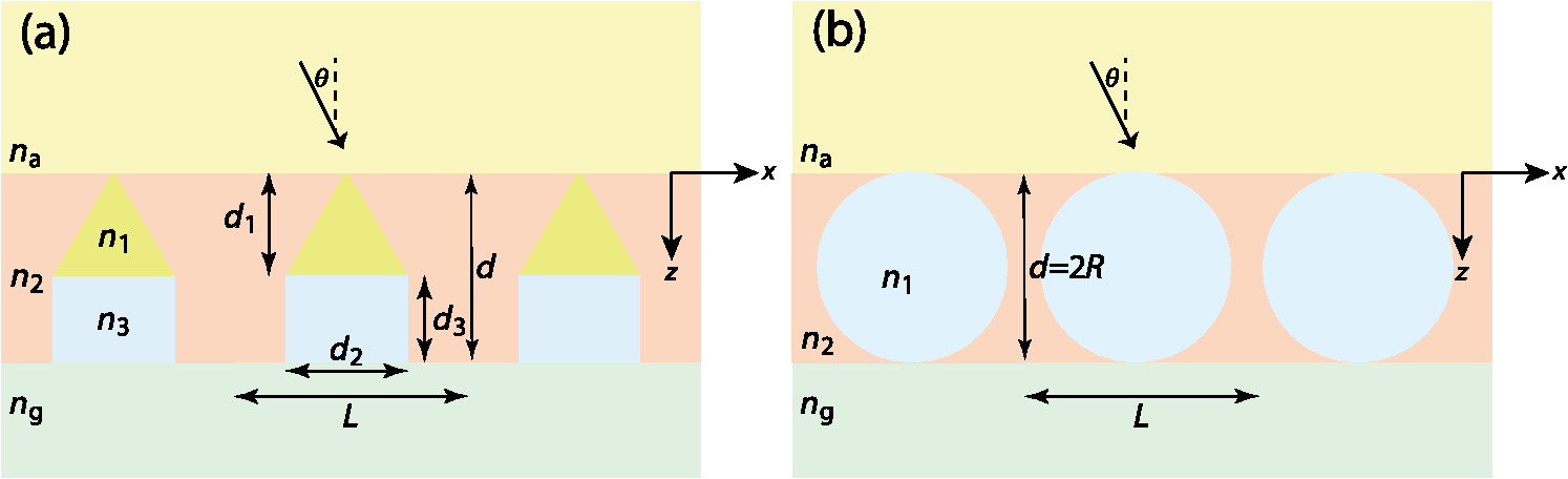 The free parameters for the splitter containing the triangle-topped rectangular grating elements in Fig. 1(a) were taken as , , , , , and , but was assumed to be fixed. The free parameters for the splitter containing the circular grating elements of radius in Fig. 1(b) were taken as , , , and . Useful improvements to the basic design were obtained. Application of the DEA indicated that significant spectrum splitting can be achieved if the angle of incidence . The paper proceeds as follows. In Sec. 2, we briefly outline the RCWA used to predict the transmission and reflection coefficients of a grating. The DEA for optimization is described in Sec. 3. For both candidate splitters, numerical results are provided in Sec. 4, allowing us to predict the degree of spectrum splitting. Concluding remarks are presented in Sec. 5. Vectors are denoted in boldface. The Cartesian unit vectors are denoted as , , and . During the application of CWA, an dependence on time was assumed for all electric and magnetic field phasors with and as the angular frequency. Furthermore, the free-space wavenumber is denoted by and the free-space wavelength by , with as the permittivity and as the permeability of free space. 2.Rigorous Coupled-Wave ApproachIn the half space , incident sunlight is modeled as a spectrum of plane waves propagating in the plane at an angle with respect to the axis. A plane wave can be either polarized or polarized. As depolarization cannot be caused by the splitter, the two polarization states can be tackled separately. 2.1.-Polarization StateThe electric field phasor of an incident -polarized plane wave of wavelength may be written as13 where and . The corresponding electric field phasors of the reflected and transmitted plane waves may be stated as8 where Components of the reflected and transmitted plane waves in Eqs. (1), (5), and (6) corresponding to are termed specular, with all the remaining components (when ) being called nonspecular.The reflection coefficients and the transmission coefficients have to be determined by solving a boundary-value problem. That task is quite easily accomplished by implementing the RCWA algorithm described in detail elsewhere.14 Briefly, the relative impermittivity in the region is expanded as a Fourier series with respect to , viz., where the coefficients have to be determined for each candidate splitter separately. The electric and magnetic field phasors in the region may then be written in terms of Floquet harmonics as where the functions and are unknown. Substituting Eqs. (9)–(11) into the frequency-domain Maxwell equations, yields a coupled system of ordinary differential equations with as the independent variable.In order to obtain a numerically tractable system, the infinite series appearing in these expressions are truncated so that , thereby obtaining 2() coupled linear ordinary differential equations. To solve this system, the coefficients are further approximated by piecewise uniform functions in using a uniform partition of the region into horizontal layers. The resulting boundary-value problem is solved by a stable marching scheme.7,8,13 2.2.-Polarization StateThe electric field phasor of the incident -polarized plane wave of wavelength may be written as13 The corresponding electric field phasors of the reflected and transmitted plane waves may be stated as8 where the reflection coefficients and the transmission coefficients have to be determined.In order to implement the RCWA, the relative permittivity in the region is expanded as a Fourier series with respect to , viz., where the coefficients are known. Equations (10) and (11) still apply. Substituting these two equations along with Eq. (16) into the frequency-domain Maxwell equations,7 yields a coupled system of ordinary differential equations with as the independent variable. Again, the infinite series appearing in these expressions are truncated so that ; the coefficients are further approximated by piecewise uniform functions in , and the resulting boundary-value problem is solved by a stable marching scheme.7,8,133.Differential Evolution AlgorithmWe implemented the DEA (Refs. 9 and 10) to seek an optimal design for each of the two candidate splitters shown in Fig. 1. The DEA is a genetic algorithm that iteratively improves a candidate solution with regard to a given measure of quality, given an initial guess in the search space together with several other candidate solutions. The algorithm attempts to avoid local minimums by stochastic choices of the updates at each step. A large space of candidate solutions can be searched, but a global minimum is not guaranteed. It is helpful to limit the search space and have a good initial choice of the free parameters. Therefore, we used this algorithm in conjunction with the conclusions gleaned from inspection of RCWA results for both candidate splitters.11,12 In brief, let denote a point in the search space for the free parameters that can be varied to obtain an optimal design, being the number of components of . The objective is to find that minimizes a given cost functional . Besides the cost functional and the search space , the algorithm requires the choice of three parameters. First, the number of candidate points in has to be chosen. These candidate points constitute the population of solutions. Next, a differential weight must be chosen to govern the mutation of three distinct points in to obtain a new donor point. Finally, a crossover probability is prescribed to select entries in a donor point to construct a new candidate point for a better solution in a process called recombination. Once the new candidate point is formed, the value of at this point is compared to the value at the current point, and the new point is used if it improves the functional’s value. Details of the algorithm itself are described in a preceding paper.11 Let us note that and for the splitter with triangle-topped rectangular grating elements, whereas and for the splitter with circular grating elements. 4.Numerical Results and DiscussionAn optimal splitter would transmit 100% of the energy to specular modes above a specified cutoff wavelength , and 100% of the energy to nonspecular modes for wavelengths below . Obviously, an ideal splitter cannot be obtained in practice. Therefore, our objective was to optimize the geometry of the two splitters shown in Fig. 1 such that (1) as much light as possible is transmitted as nonspecular Floquet harmonics for and (2) as much light as possible is transmitted as the specular Floquet harmonic for . Since the nonspecular Floquet harmonics transport energy in directions different from the specular direction, different energy-harvesting devices can be used for the two spectral regimes. Accordingly, we set the cost functional where the penalty factor , and is the Heaviside step function. The chosen cost functional contains the weighted difference between the transmittance and the Heaviside step function in the norm. The penalty factor can be used to tune the functional, but we chose not to explore that issue here and simply set . We also elected not to penalize the reflectances since by driving the transmittances toward unity, we forced the reflectances toward zero.For all results presented here, we used horizontal layers of thickness 5 nm for the piecewise-uniform approximation of the coefficients and for , and we fixed after ensuring that the principle of conservation of energy13 was satisfied with an error <0.01%. Furthermore, we selected , , and for the DEA. Although good separation of specular and nonspecular transmissions for a wide range of angles of incidence is highly desirable, the process of averaging over —in addition to averaging over —would greatly increase computational time. So we started by fixing for optimization, but then explored how the optimal splitters would perform at other angles of incidence. Let us note that , , , and do not depend on the sign of , because the unit cells of both candidate splitters are symmetric about the axis. For the numerical results presented in this paper, we chose SF11 glass as the material in the half space of transmission. The refractive index as a function of is available in the literature.15 As mentioned in the previous section, we set . Both of these choices are consistent with the use of spectrum splitters for solar cells. Fixing and , we set the wavelength for the switch between specular and nonspecular scattering. We also assumed to be real and independent of , thereby confining the scope of our results to materials with weak dissipation and weak dispersion in the chosen spectral regime. All computational codes were written in MATLAB® and implemented on a LINUX machine Dell PowerEdge R620 configured with 15K SAS Drives and 320 GB of RAM. Version 2014a of 64-bit MATLAB® was used. 4.1.Optimization of the Splitter with Triangle-Topped Rectangular Grating ElementsWe began with the optimization of the splitter shown in Fig. 1(a). We set to be the -dependent refractive index of a specific composite material (glass: 47% titania and 53% silica) shown in Fig. 2. We set as the initial guess for the DEA. As mentioned in Sec. 3, this initial guess for was used as one member of the candidate points in the DEA.Fig. 2Refractive index of the chosen composite material (containing 47% titania and 53% silica) as a function of . 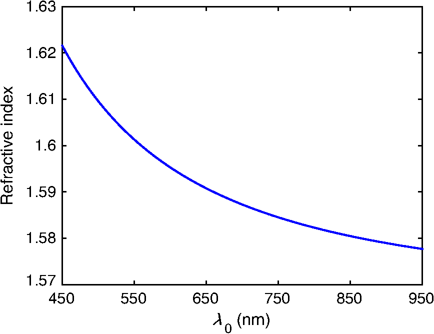 Figure 3 presents the spectrums of , , , and for with the initial guess (28). At both angles of incidence, there is a tendency to shift between specular and nonspecular transmission as the wavelength changes, but the effect is not large. Fig. 3, , , and as functions of for the splitter with the triangle-topped rectangular grating elements described by the initial guess (28): (a) and (b) . 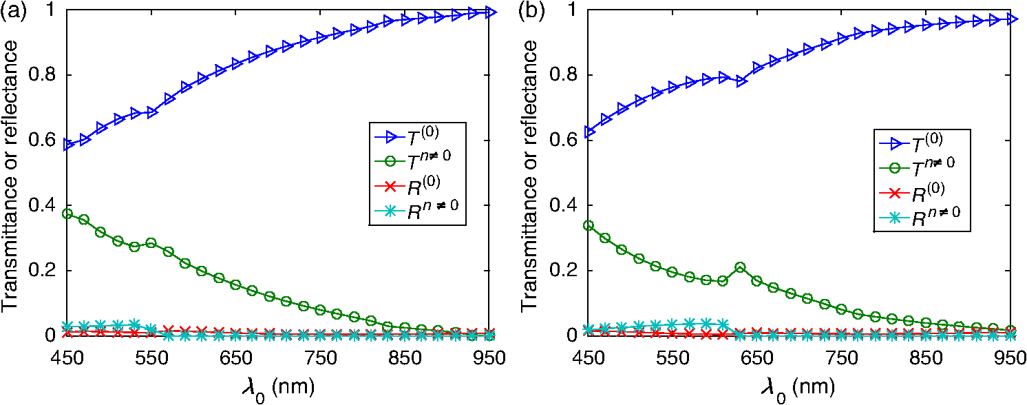 For optimization, the free parameters were constrained to lie in the following search space : As the DEA allows the user to set a minimum step size for updating each free parameter in the search space, we used the following minimum step sizes: 10 nm for ; 5 nm for and ; and 0.1 for , , and .After optimization for , we obtained the following parameters using 100 iterations of the DEA: The progress of the cost functional toward the optimal design is shown in Fig. 4. The DEA reduced the value of by within 50 iterations.Fig. 4Values of the cost functional during the first 50 iterations of the differential evolution algorithm (DEA) for the splitter with the triangle-topped rectangular grating elements. These calculations were done for . 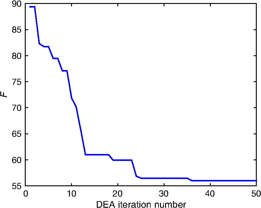 Figure 5 presents the spectrums of , , , and for with the optimal parameters (30). Clearly, the short-wavelength behavior is much improved in comparison to Fig. 3. Furthermore, there is a definite switch around , as desired. The switch blue shifts at a more oblique incidence, per the right panel of Fig. 5. Fig. 5Same as Fig. 3, except using the optimal parameters (30): (a) and (b) . Optimization was performed for and the crossover of the specular and nonspecular transmittances occurs at as desired. The crossover point blue shifts for .  In order to present a complete picture of the behavior of the splitter after optimization, in Fig. 6 we present density plots of and as functions of and . Ideally, the left panel of Fig. 6 would be dark to the left of , while the right panel would reverse this. Provided that the incidence is not very oblique (say, ), there is an obvious switch in energy between the specular and nonspecular modes of transmission, but this switch occurs at somewhat shorter wavelengths as the angle of incidence shifts from 0 deg. 4.2.Optimization of the Splitter with Circular Grating ElementsAs the splitter with the triangle-topped rectangular grating elements considered in Sec. 4.1 would be difficult to manufacture, we turned our attention to the splitter with circular grating elements shown in Fig. 1(b). The following search space was fixed: We used the following minimum step sizes: 10 nm for , 0.01 for , and 0.1 for and .The initial guess for the DEA was chosen as follows: With these parameters, the reflection and transmission characteristics of the splitter before optimization are shown in Fig. 7. While a tendency toward spectrum splitting is evident, the splitter does not perform well in the short-wavelength regime.Fig. 7, , , and as functions of for the splitter with the circular grating elements described by the initial guess (32): (a) and (b) . 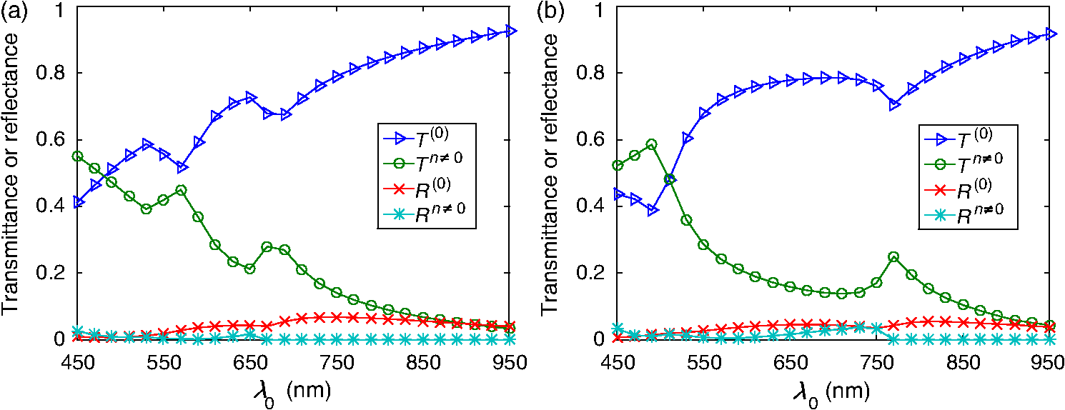 4.2.1.Optimization atApplication of the DEA (with fixed) provided definite improvement. The progress of the optimization scheme is shown in Fig. 8. The cost functional decreased by in the first 10 iterations (with the first iteration alone accounting for ) and stayed flat thereafter. The parameters , , , and showed similar trends as the DEA progressed, as shown in Fig. 9. Fig. 8Values of the cost functional during the first 50 iterations of the DEA for the splitter with the circular grating elements. These calculations were done for . 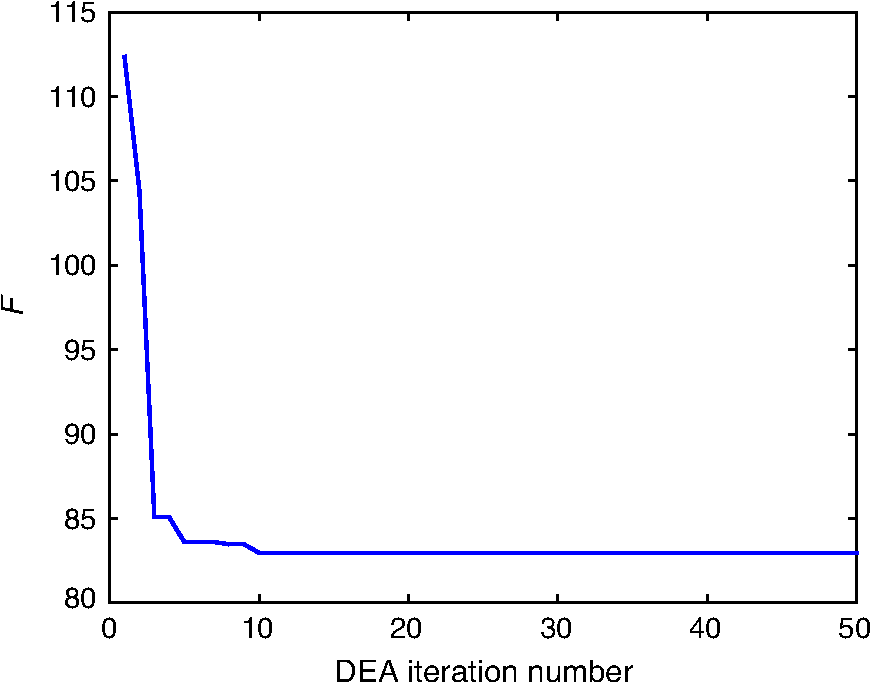 Fig. 9Parameters , , , and during the first 50 iterations of the DEA for the splitter with the circular grating elements. These calculations were done for . The initial guesses are not shown. 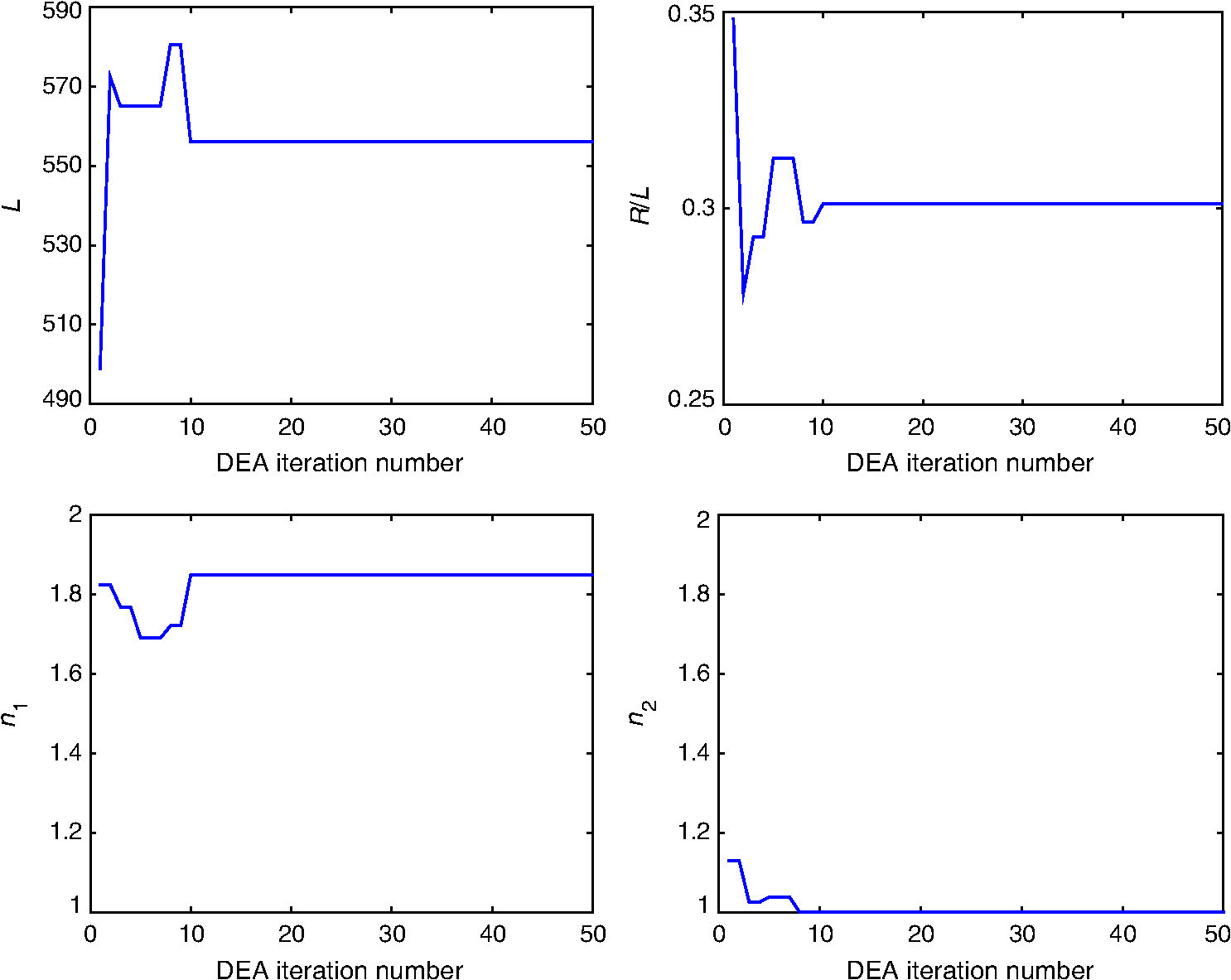 After 100 iterations of the DEA, we obtained the following optimal parameters: With these parameters, the reflection and transmission characteristics of the device are shown in Fig. 10. Despite the relatively small decrease in the cost functional during optimization, the left panel of Fig. 10 () shows markedly improved short-wavelength behavior with an obvious splitting around .Fig. 10Same as Fig. 7, except using the optimal parameters (33): (a) and (b) . Optimization was performed for and the crossover of the specular and nonspecular transmittances occurs at as desired. The crossover point blue shifts for . 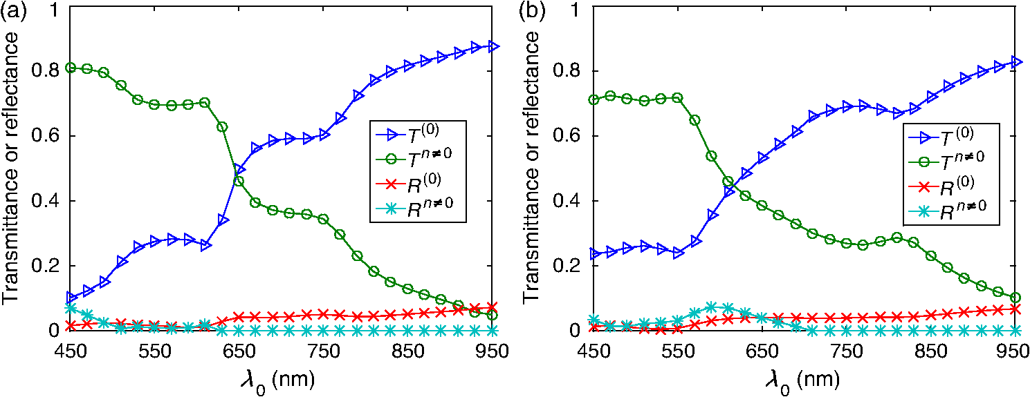 In order to further illustrate the dependence of the splitter’s performance on the angle of incidence , in Fig. 11 we present density plots of and as functions of and . In comparison to the splitter with triangle-topped rectangular grating elements (Fig. 6), the splitter with circular grating elements shows a poorer performance for more oblique incidence. 4.2.2.Optimization atNext, we chose to optimize at in order to try to improve the performance of the device away from normal incidence. Through trial and error in search of a better result than in Sec. 4.2.1, we also enlarged the search space as follows: However, we still used the initial guess (32).After 100 iterations of the DEA (with fixed), we obtained the following optimal parameters: The progress of the optimization scheme is shown in Fig. 12, the cost functional decreasing by in the first 20 iterations and staying flat thereafter.Fig. 12Values of the cost functional during the first 50 iterations of the DEA for the splitter with the circular grating elements. These calculations were done for . 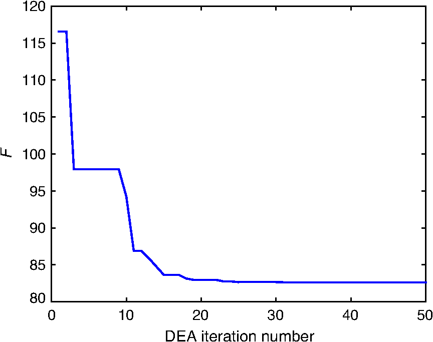 The reflection and transmission characteristics of the optimal device are shown in Fig. 13. Even though the functional for optimization at acquires the same value as for optimization at , as may be gleaned from comparing Figs. 8 and 12, the performance (Fig. 13) of the solution (35) is rougher than the performance (Fig. 10) of the solution (33). Nevertheless, the crossover at occurs at both values of . However, note that the optimal choice involves for in Sec. 4.2.1, but for the optimal choice for . This reversal needs to be explained and we do that in Sec. 4.2.3, as well as investigating further the shape of the cost functional as a function of the free parameters. Fig. 13Same as Fig. 7, except using the optimal parameters (35): (a) and (b) . Optimization was performed for and the crossover of the specular and nonspecular transmittances occurs at as desired for both angles of incidence. 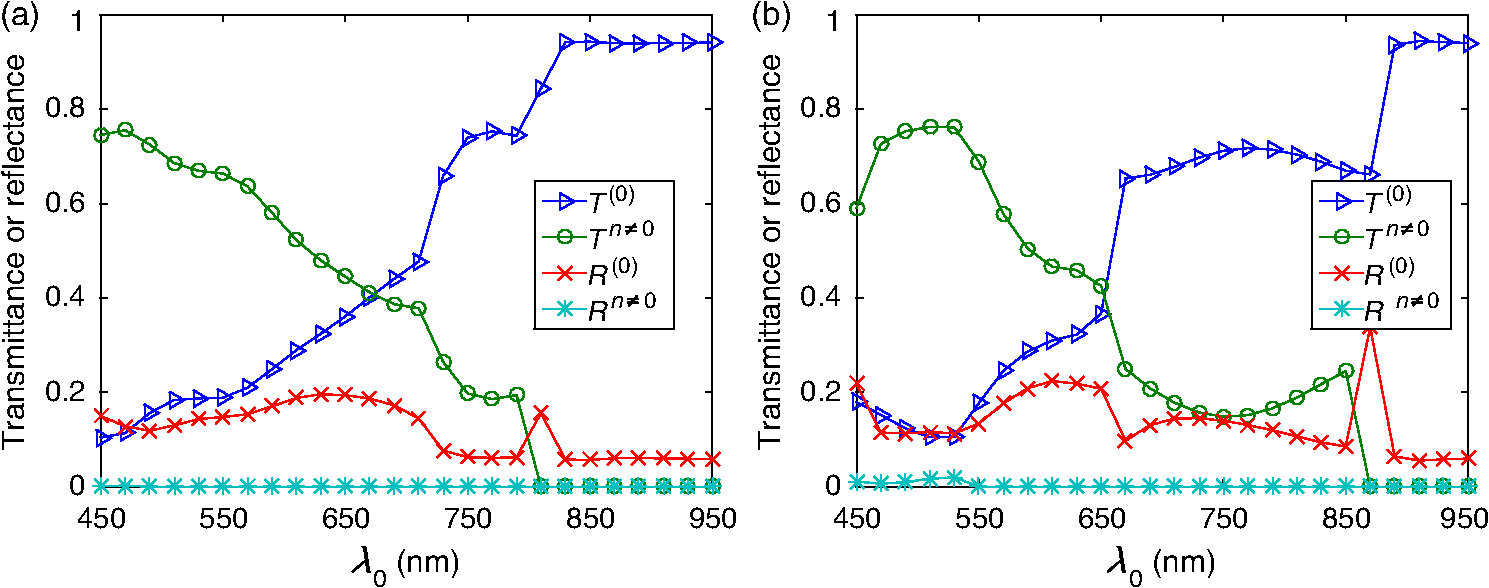 Density plots of and as functions of and are presented in Fig. 14. Again, in comparison to the splitter with triangle-topped rectangular grating elements (Fig. 6), the splitter with circular grating elements shows a poorer performance for more oblique incidence. In comparison to Fig. 11, the crossover in Fig. 14 at is sharp and blueshifts steadily as the incidence becomes more oblique. The difference is due to optimizations performed for different values of . Fig. 14Density plots of (a) and (b) against and for the splitter with the circular grating elements described by the optimal parameters (35). This figure should be compared to Fig. 11. 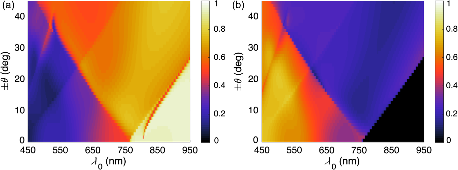 4.2.3.Comparative analysisThe spectrums in Fig. 13 are more irregular than in Fig. 10 and are accompanied by a reversal of high refractive index and low refractive index regions. Thus, we investigated the functional to help confirm that the optimum had indeed been reached. First, we fixed , , and (i.e., at their optimal values), and then plotted against . Figure 15(a) shows that as a function of has a single minimum—at , the value yielded by the DEA as the optimal choice (35). Fig. 15(a) as a function of when , , and , (b) as a function of and when and , and (c) as a function of when the remaining parameters are fixed at their optimal values: , , and .  Next, we fixed and at their optimal values, and plotted against and in Fig. 15(b). In this case, there are two local minima. One has , the other . Both minima give the same order of magnitude of , and DEA chooses correctly in Sec. 4.2.2. In Sec. 4.2.1, this choice was ruled out by the stringent constraint on in (31). The local minimum when (in Sec. 4.2.1) also gives a small value of . Finally, we fixed the parameters , , and . Figure 15(c) presents as a function of the ratio . Clearly, reaches the global minimum when as predicted by DEA. Besides the global minimum, the graph shows that has two other local minima. These local minima could trap a gradient search algorithm16 and justify the use of the DEA or some other algorithm designed to avoid local minima. 5.Concluding RemarksWe have demonstrated with two candidate devices that the combination of RCWA and DEA is a useful tool for designing gratings intended for splitting the solar spectrum. By adjusting a reasonable initial guess and defining a suitable search space, we can optimize the structural and constitutive parameters of candidate splitter designs. Greater optimization would require us to allow more changes in the design (e.g., perhaps shapes) but would require more computational time and might result in structures that are hard to manufacture. Experimental validation of a structure similar to the optimized splitter with circular grating elements is being pursued. AcknowledgmentsPartial support for this work was provided by the US National Science Foundation via Grant Nos. DMR-1125590 and DMR-1125591. A.L. acknowledges ongoing support of his research by the Charles Godfrey Binder Endowment at Penn State. ReferencesE. D. Jackson,
“Areas for improvement of the semiconductor solar energy converter,”
(2015) March ). 2015). Google Scholar
A. G. Imenes and D. R. Mills,
“Spectral beam splitting technology for increased conversion efficiency in solar concentrating systems: a review,”
Sol. Energy Mater. Sol. Cells, 84
(1–4), 19
–69
(2004). http://dx.doi.org/10.1016/j.solmat.2004.01.038 SEMCEQ 0927-0248 Google Scholar
J. H. Karp and J. E. Ford,
“Multiband solar concentrator using transmissive dichroic beamsplitting,”
Proc. SPIE, 7043
(1), 70430F
(2008). http://dx.doi.org/10.1117/12.793906 PSISDG 0277-786X Google Scholar
J. D. McCambridge et al.,
“Compact spectrum splitting photovoltaic module with high efficiency,”
Prog. Photovolt.: Res. Appl., 19
(3), 352
–360
(2011). http://dx.doi.org/10.1002/pip.1030 PPHOED 1062-7995 Google Scholar
G. D. Barber et al.,
“Utilization of direct and diffuse sunlight in a dye-sensitized solar cell—silicon photovoltaic hybrid,”
J. Phys. Chem. Lett., 2
(6), 581
–585
(2011). http://dx.doi.org/10.1021/jz200112m 1948-7185 Google Scholar
G. Kim et al.,
“Increased photovoltaic power output via diffractive spectrum separation,”
Phys. Rev. Lett., 110
(12), 123901
(2013). http://dx.doi.org/10.1103/PhysRevLett.110.123901 PRLTAO 0031-9007 Google Scholar
M. G. Moharam, E. B. Grann and D. A. Pommet,
“Formulation for stable and efficient implementation of the rigorous coupled-wave analysis of binary gratings,”
J. Opt. Soc. Am. A, 12
(5), 1068
–1076
(1995). http://dx.doi.org/10.1364/JOSAA.12.001068 JOAOD6 0740-3232 Google Scholar
M. Faryad and A. Lakhtakia,
“Grating-coupled excitation of multiple surface plasmon-polariton waves,”
Phys. Rev. A, 84
(3), 033852
(2011). http://dx.doi.org/10.1103/PhysRevA.84.033852 PLRAAN 1050-2947 Google Scholar
R. Storn and K. Price,
“Differential evolution—a simple and efficient heuristic for global optimization over continuous spaces,”
J. Glob. Optim., 11
(4), 341
–359
(1997). http://dx.doi.org/10.1023/A:1008202821328 JGOPEO 0925-5001 Google Scholar
K. V. Price, R. M. Storn and J. A. Lampinen, Differential Evolution: A Practical Approach to Global Optimization, Springer, Berlin
(2005). Google Scholar
M. Solano et al.,
“Optimization of the absorption efficiency of an amorphous-silicon thin-film tandem solar cell backed by a metallic surface-relief grating,”
Appl. Opt., 52
(5), 966
–979
(2013). http://dx.doi.org/10.1364/AO.52.000966 APOPAI 0003-6935 Google Scholar
M. Solano et al.,
“Optimization of the absorption efficiency of an amorphous-silicon thin-film tandem solar cell backed by a metallic surface-relief grating: erratum,”
Appl. Opt., 54
(3), 398
–399
(2015). http://dx.doi.org/10.1364/AO.54.000398 APOPAI 0003-6935 Google Scholar
J. A. PoloJr., T. G. Mackay and A. Lakhtakia, Electromagnetic Surface Waves: A Modern Perspective, Elsevier, Waltham, MA
(2013). Google Scholar
P. Lalanne and G. M. Morris,
“Highly improved convergence of the coupled-wave method for TM polarization,”
J. Opt. Soc. Am. A, 13
(4), 779
–784
(1996). http://dx.doi.org/10.1364/JOSAA.13.000779 JOAOD6 0740-3232 Google Scholar
(
(2015) http://refractiveindex.info/legacy/?group=GLASSES&material=SF11 January ). 2015). Google Scholar
H. Bai, C. K. Kwong and Y. C. Tsim,
“Process modelling and optimisation using artificial neural networks and gradient search method,”
Int. J. Adv. Manuf. Technol., 31
(7–8), 790
–796
(2007). http://dx.doi.org/10.1007/s00170-005-0256-x 0268-3768 Google Scholar
BiographyLi Fan received his BS degree in mathematics in 2004 from the University of Science and Technology of China. He then received his MA in statistics and his PhD in mathematics (2013) from Wayne State University. He is now a postdoctoral research scholar at the University of Delaware. His research interests include the analysis and implementation of discontinuous Galerkin methods for solid and structural mechanics, superconvergence phenomena, numerical methods in computational electromagnetism, and inverse scattering. Muhammad Faryad received his MSc and MPhil degrees in electronics from Quaid-i-Azam University in 2006 and 2008, respectively, and his PhD in 2012 in engineering science and mechanics from the Pennsylvania State University, where he served as a postdoctoral research scholar from 2012 to 2014. He is now an assistant professor of physics at the Lahore University of Management Sciences, Pakistan. His research interests include modeling of thin-film solar cells, electromagnetic surface waves, and sculptured thin films. Greg D. Barber received all of his degrees from the Pennsylvania State University: BS physics (1991), BS ceramic science and engineering (1991), MS materials (1995), and PhD materials (1998). He is a staff member in the Penn State Institute for Energy and Environment after a postdoctoral appointment (1998 to 2000) and staff tenure (2000–2002) at the National Renewable Energy Laboratory. His research focuses on solar radiation, thin-films, and scalable materials and processing for solar-energy production. Thomas E. Mallouk received his PhD degree in 1983 from the University of California, Berkeley under the direction of Neil Bartlett, and was a postdoctoral fellow with Mark Wrighton at MIT. He is currently Evan Pugh Professor at the Pennsylvania State University. His research focuses on the synthesis of nanomaterials and their applications to problems in chemistry, physics, and biology. Peter B. Monk received his BA degree (1978) in mathematics from Cambridge University and his MS (1981) and PhD (1982) degrees in mathematics from Rutgers University, Piscataway, New Jersey. He is currently UNIDEL professor in the Department of Mathematical Sciences at the University of Delaware. His research focuses on numerical analysis and scientific computing, with particular emphasis on numerical methods in computational electromagnetism and inverse scattering. Akhlesh Lakhtakia is the Charles Godfrey Binder (Endowed) professor of engineering science and mechanics at the Pennsylvania State University. He is a fellow of SPIE, OSA, APS, IoP, and AAAS. He was the sole recipient of the 2010 SPIE Technical Achievement Award. His current research interests include circular polarization and Beltrami fields, electromagnetic surface waves, thin-film solar cells, sculptured thin films, mimumes, bone refacing, bioreplication, and forensic science. |